To Define Topology
-
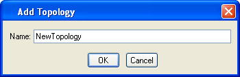
Right-click the Persistent Topology node and select Add Topology for each topology to be added.
The Add Topology dialog opens.
- Enter a name for the topology and click OK.
-
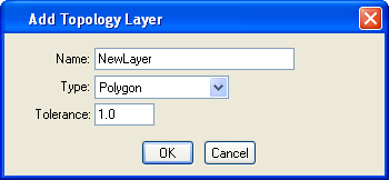
Right-click the new topology and select Add Topology Layer for each layer to be added.
The Add Topology Layer dialog opens.
-
Enter a name for the new topology layer and a type.
Type can be line, point, or polygon. Typically, polygon features go in polygon layers, line string features in line layers, and cell features in point layers.
-
Enter a tolerance.
This determines if two points may be considered equal. Use a small value appropriate for the items being modeled and the design file’s working units. For example, if the engineering units of a design file are meters, a valid tolerance choice might be 0.25.
-
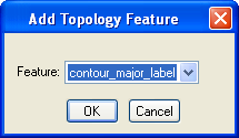
Right-click the new topology layer and select Add Topology Feature for each feature to be added.
The Add Topology Feature dialog opens.
- Select the feature to be added to the topology layer and click OK.