| Layout
|
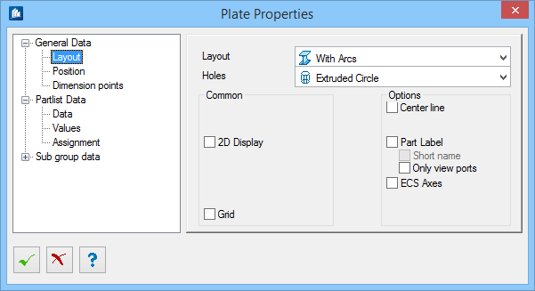
Here, you specify how the plate has to be depicted.
|
| Holes
|
Here, you specify the depiction of drill holes.
|
| Modeller
|
The component part is displayed by means of the
facet-modeler. Normally, the software independently decides when the modeler
has to be used for depiction. However, you can explicitly define it using this
option. If the modeler has to be used, you cannot switch it off.
|
| 2D Display
|
A calculated 2D-depiction depending on the current
view direction is displayed instead of standard 3D-depiction.
|
| Grid
|
A plate grid is displayed on the upper side of the
plate. This grid represents a gridiron or similar things.
|
| Centerline
|
The centerline of the plate is displayed
|
| Part Label
|
The object name will be displayed dynamic at the
object.
|
| Short Name
|
The name of the component part is displayed
dynamically at the part. The position depends on the angle of vision. The
settings are made in the global settings.
|
| Only view ports
|
The element names will be displayed in an
activated and prepared view port.
|
| ECS Axes
|
The Entity Coordinate System is displayed. It mainly
serves for verifying purposes.
|