Model Annotation
Used to assemble and manage a list of model annotation styles. When you change the model annotation styles, you change the display of annotation information. There are three ways to specify model annotation: by changing symbology for member lines; by labeling elements; and by labeling analytical model members.
Accessed from: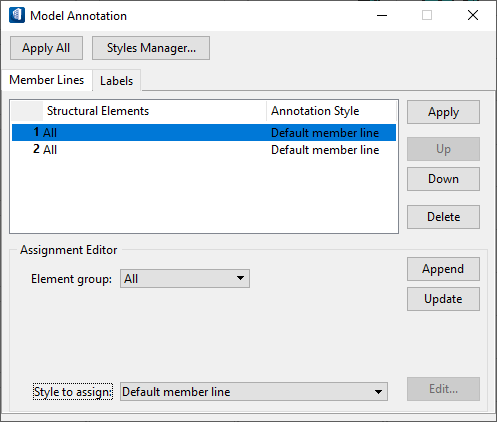
By default, member lines are drawn using the same symbology as the element you are drawing. If you draw a steel beam that is represented in the purple and line weight 1, the associated member line by default is drawn in the same color and weight and therefore may be difficult to see. You can change the appearance of the member line by specifying in the Model Annotation dialog a different symbology for the member line. The element will still follow its default symbology, but the member line will look different and therefore stand out. The member line is drawn on a level different from the element, so that you can turn off the levels displaying the element and yet still display the member line.
By default, labels do not appear in the drawing, to keep the drawing from being too cluttered. The Model Annotation dialog lets you place labels that can contain any of the information you established when placing the structural element (your entries for Class using the Place Beam or some other tool, for example). When you decide the labels you want to place, click the Labels tab and complete the dialog fields as described below. All data that fits the label parameters will display.
Labels are placed separately from the structural members. This can be very helpful if you do not want to display the elements, but do want to display the labels. An example of when you may want to do this is if you are viewing the analytical member lines and do not want to see the elements, but would like to see the annotations.
| Setting | Description |
|---|---|
| Apply All | Applies all types of model annotation that have been changed in both the Member Lines and Labels tabs. The annotation is applied in order of appearance in the Member Lines or Labels tab, and an element is affected only once. If a second entry would also include the element by its definition, the element will not reflect this second annotation style change. |
| Styles Manager... | Opens the Model Annotation Styles Manager dialog. The Model Annotation Styles Manager dialog also opens when you click Edit in the Assignment Editor section. |
Import Model Annotations
In the key-in window, type:
- [filename] is the DGN that contains the model, and
- [modelname] is the model itself.
- If you currently have open SteelFrame.dgn, have created a new model within it, and you want to import the model annotations of FirstFloor, you can skip the specification of the DGN and enter STFANNOTATE IMPORT ASSIGNMENTS,FirstFloor
- If you are importing the model annotations from the default model of the currently open DGN, but you have another model open, you can enter this key-in command: STFANNOTATE IMPORT ASSIGNMENTS,Default
- If you are importing the default model of a DGN, you can omit the model name in your key-in command: STFANNOTATE IMPORT ASSIGNMENTS TFDIR_SEED:3dEnglishStruct.dgn.