View Attributes dialog - Building Panel General tab
Selecting
 opens the View Attributes dialog.
By default, this is the first icon in every view window toolbar. Initially, if
a Building dynamic view is not available, the View Attributes dialog Building
panel settings are limited to controls used to activate the full set of
Building dynamic view controls.
opens the View Attributes dialog.
By default, this is the first icon in every view window toolbar. Initially, if
a Building dynamic view is not available, the View Attributes dialog Building
panel settings are limited to controls used to activate the full set of
Building dynamic view controls.
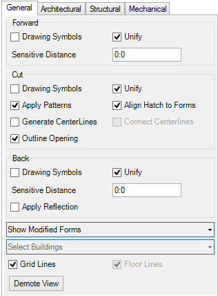
The full set of Building panel controls are available when a
Building dynamic view is active. Several tabs are enabled to apply drawing
rules for individual Building applications. Settings vary among the tabs as
they apply to each specific Building application. The General tab provides
drawing symbology settings. These settings enable modifications to be applied
immediately without the need to recalculate drawing definitions.

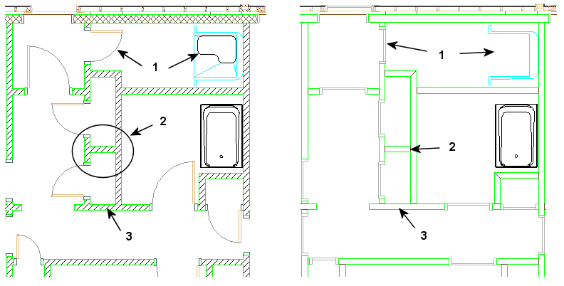
Note: There are at least
three types of Dynamic Views. They are Active Views, Dynamic
Views, and Building Dynamic Views. It is important to understand
each one and their differences.
- An Active View allows you to store view parameters and reapply them to your design later to quickly achieve the same orientation, level on/off state, and rendering mode for example. Dynamic Views and Building Views build on this concept. The Active View stores presentation settings and parameters in the Presentation panel.
- A Dynamic View is a Saved View that stores additional information, such as the type of saved view and whether the model is a design model or a sheet model. The Dynamic View also stores presentation settings and parameters in the View panel.
- A Building Dynamic View is a Saved View that incorporates the parameters of both the Active View and the Dynamic View. The Building Dynamic View applies additional information such as Forward, Cut, and Back view drawing symbols, sensitive distances, and patterning. And Architectural, Mechanical, and Structural drawing rules are applied in this view using tabs in the Building panel.
| Setting | Description |
|---|---|
| Forward (group box) |
|
| Cut (group box) |
|
| Back (group box) |
|
| Show Modified Forms | These settings options temporarily override the
display of modified components until the file is saved. After the save
operation, the process is restarted.
|
| Show Grid System | When there are one or more grid systems defined in a project using the Grid Systems Manager , you can automatically generate grid system graphics in the dynamic view drawing model during the auto annotation process. Turn this setting on to automatically generate the grid system annotations in dynamic view references attached to a drawing model. |
| Show Elevation | When on, the dynamic view displays only gridlines, only floor elevation lines, both gridlines & elevations, or neither gridlines nor elevations for the given Elevation. Show Elevation is greyed out if the dynamic view is not an Elevation. |

|
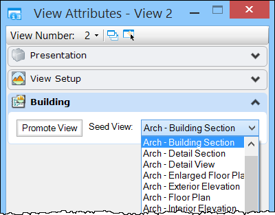
Clicking "demotes" a Building view back to a normal Dynamic View. This action closes the application tabs in Building panel. |