(Technology Preview) Perforators
A Perforator is a
parametric solid that acts as a cutting element on a target element. The target
element can be a parametric solid or a SmartSolid. The simplest example of a
perforator is a door that when placed on a wall cuts the wall to allow the door
to fit inside the wall.
The general workflow for using perforators is given
below.
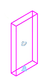
- Create a parametric cell having a parametric solid(s).
- Use the Define Perforator tool to tag the parametric solid as a perforator.
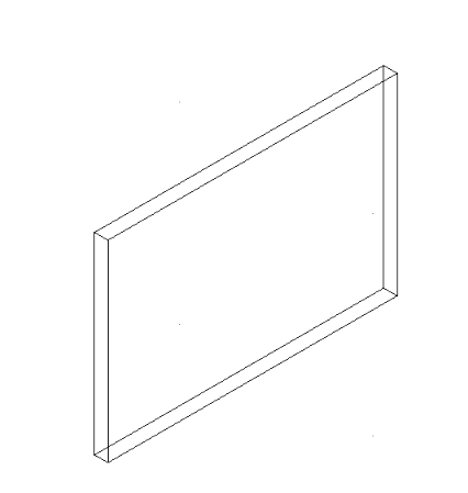
- Attach the parametric cell to the DGN file that contains the target element on which the perforation is to be performed. The target element can be a parametric solid or a SmartSolid.
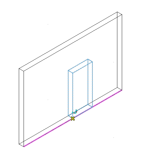
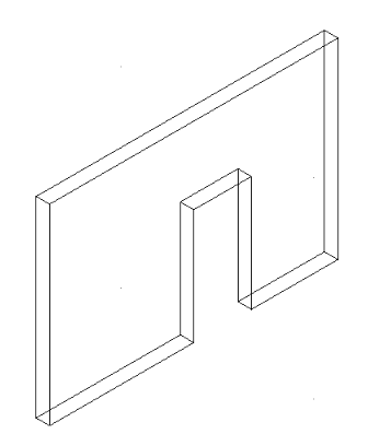
- Hover the cursor on the target element, such that the parametric cell overlaps the target element. Observe that the perforator previews as a blue dotted line.
- Place the cell on the target element. Observe that the perforator cuts the target element to the shape of the perforator.
Additionally, you can also apply variations to the perforator. So in case of the door-wall example, you can apply variations for different door sizes and the cut in the wall will change according to the door size.
Once placed, the parametric cell containing perforator acts any other parametric solid. You can manipulate the cut using Move and Rotate commands. Also, deleting the placed cell undoes the cut on the target element.
Define Perforator
 The
Define Perforator tool is used to define an
parametric solid as a perforator. Once defined, perforator properties are
applied to the parametric solid.
The
Define Perforator tool is used to define an
parametric solid as a perforator. Once defined, perforator properties are
applied to the parametric solid.
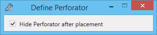
| Setting | Description |
|---|---|
| Hide Perforator after placement | Hides the perforator after it is placed on the target element. |
To Place a Perforator
Make sure you have the perforator attached as a cell in
the Cell Library dialog.
- In the Cell Library
dialog, right-click on the cell and select
Place Cell.
The Place Parametric Cell tool starts.
- If required, rotate the cell.
- Place the cursor at a
point on the target element where you want the cut to be placed.
Observe that the cut is previewed as a dotted line.
- Enter a data point.