Fence Tab, DGN/DWG Settings
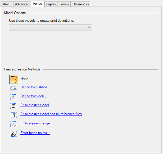
Contains controls used to specify fence creation and model selection methods for selected or new print definitions. The Fence tab appears in the Modify Properties dialog and in the Print Styles dialog.
| Setting | Description |
|---|---|
| Use these models to create print definitions | (Visible only when the Print Definition Creation Options dialog or Define Print Styles dialog is selected.) List box that lets you choose the models to print.
|
| None | Indicates that you do not want to define a fence. |
| Define from shape | Opens the Define from shape dialog, which is used to specify the plot area indirectly by describing shapes whose actual coordinates define the print area. |
| Define from cell | Opens the Define from cell dialog, which is used to specify the plot area indirectly by describing a cell whose actual coordinates define the print area. |
| Fit to master model | The print area is automatically calculated to include every element in the master model. The fence points are displayed in the Fence points list box. |
| Fit to master model and all reference files | The print area is automatically calculated to include every element in the master model and all references. The fence points are displayed in the Fence points list box. |
| Fit to element range | Opens the Fit to element range dialog, which is used to specify the plot area indirectly by describing a fence whose coordinates are based on the range of specified elements. The fence points are displayed in the Fence points list box. |
| Enter fence points | Opens the Enter fence points dialog, which is used to specify the fence points that define the print area. |