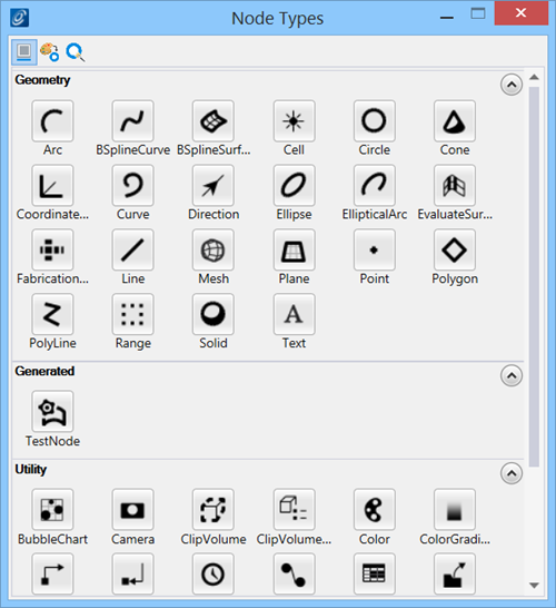
Node Types dialog
Used to create new nodes and view node techniques.
| Setting | Description |
|---|---|
| Show names |
When on (default), node names are displayed. When off, node names are hidden. Useful for maximizing the application window area. |
| Apply symbology |
When on, symbology settings from the Attributes toolbox are applied to the selected node's graphics. When off (default), you can define the symbology of a node’s properties in the Node Properties dialog, in the general properties category. |
| Edit new nodes |
When on, the Node Properties dialog is automatically opened with the selected node's properties available for editing. When off (default), the Node Properties dialog is not opened. |
| Geometry nodes |
Contains geometric nodes such as Line, Arc, Polygon, Surface, Mesh, Solid, and Text. |
| Utility nodes |
Contains special nodes that act on other nodes in the model such as ClipVolume, Slider, Expression, and ReferenceAttachment. |
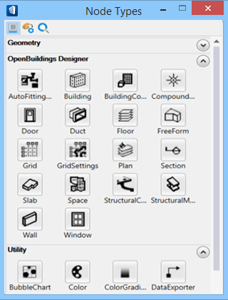
| OpenBuildings Designer |
Contains nodes for placing OpenBuildings Designer components such as Walls, Slabs, Spaces, Doors and Windows, and StructuralMember. |
| Techniques | The node pop up menu displays techniques available for the selected node. Each technique contains a list of input properties that must be defined in order to create the node. |
| Tooltips |
Hover the pointer over a node to display information |
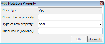
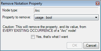
| Notation Properties | Accessible from the node pop up menu (right click on the node). Used to add and remove notation properties for selected nodes.
|