Platform Design Example
You can easily create modified girders in platform constructions by first laying the shapes to be changed as a whole and then dividing them at their rafters. Conversely, rafters can be removed rapidly and the changes at this position cancelled.
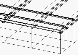
Assume you want to design a platform using the following shapes: platform beams IPE 300, platform edge girders IPE 200, headers HEA 120. Create a working area with these dimensions and insert the shapes at the construction lines. Overlaps can be ignored.
Orient to the "top" view and use the Element Modification dialog to process the elements. Similarly, you can process the Y-axes of the general overview in "front" oriented view.
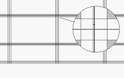
Since IPE 300 has a flange width of 150 mm, enter the
value 75 in the
Distance field and click
 (Divide). Zoom into the intersections one after the
other, select the uncut part of the cross girder to be separated, and the
construction line as cutting line.
(Divide). Zoom into the intersections one after the
other, select the uncut part of the cross girder to be separated, and the
construction line as cutting line.
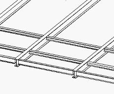
You have several shape parts now that can be connected.
Insert each partial shape. This eliminates the risk for
dimensional errors. If you want to remove beams, you can easily close the gaps
between cross girders and create a continuous shape by clicking
 (Connect).