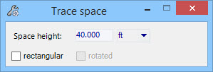
Trace space
Used to define the
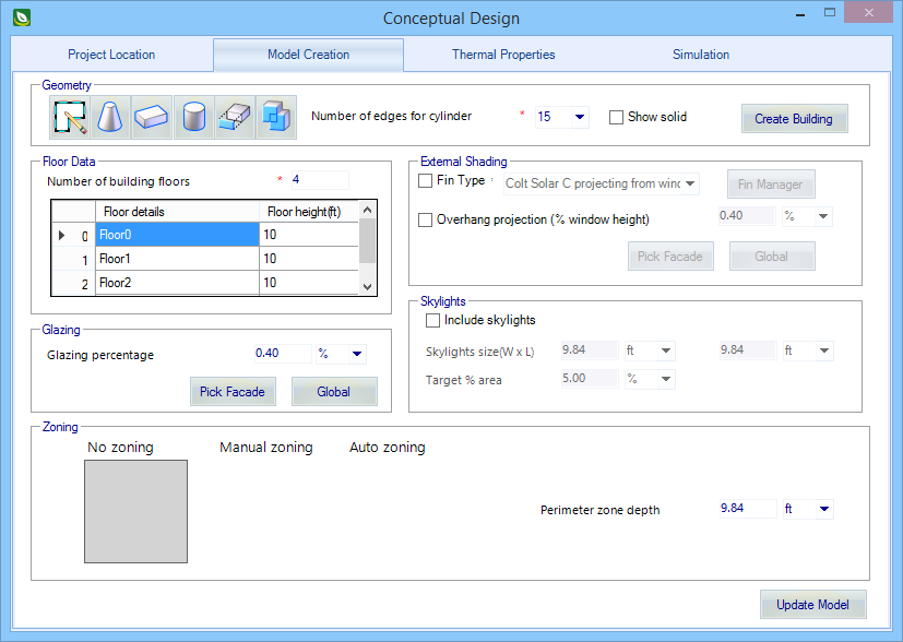
overall building shape (floor plan) when creating a
Conceptual Design for
Preliminary Simulation of Energy Performance.
Accessed from:

Trace space is similar to Trace Room in that it is used to draw a shape to define a space (room), but does not have the room creation options as for Trace Room.
| Setting | Description |
|---|---|
| Space height | Used to display the overall height of the space being traced. Space height is set in the Conceptual Design dialog's Model Creation tab (Floor Data setting). Space height cannot be overridden in the Trace space tool settings window. |
| Rectangular | When on, the space being traced is locked into a rectangular shape. Checking the Rectangular option also enables the Rotated option. If the Rotated option is unchecked, the rectangular room's width and height are aligned with the X and Y axes regardless of the AccuDraw Compass orientation. Tracing a rectangular shaped space without using the Rotated option requires entering two data points; the opposite diagonal corners of the rectangle. |
| Rotated | When on, the rectangular space being traced can be rotated about the first identified space corner. The second data point entered determines the angle of rotation, and also rotates the AccuDraw Compass. The third data point entered establishes the opposite diagonal corner of the rectangular space. The rotation, once established is independent of the AccuDraw Compass. |
Tip: Units
Display – Units are displayed using the default system of units that was
defined for the project, but can be
changed to display using
alternative units.