| General tab
|
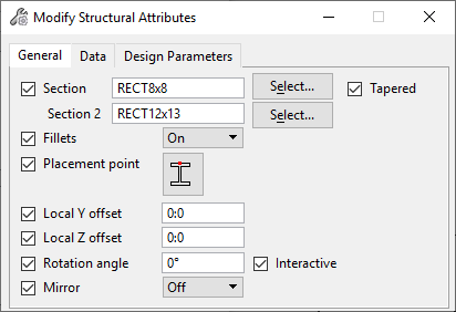
Contains controls for modifying the selected member
or members physical attributes such as section data and member orientation.
- Section — Used to
enter a new section definition for the selected member or members. Clicking the
magnifying glass icon opens the Structural Sections dialog. From here, section
definitions are browsed.
- Tapered — When on,
two section data options are enabled to modify tapered members; One for end 1
and the other for end 2.
- Section 2 — Used to
enter a new second section definition for the selected tapered member or
members. Clicking the magnifying glass icon opens the Structural Sections
dialog. From here, section definitions are browsed.
- Fillets — When on,
fillets are constructed between the flange and web surfaces on the selected
structural member or members.
- Placement Point —
Modifies the location of the baseline relative to the member section by
selecting from the drop list items. The Centroid placement point is enabled
only if the section is fully symmetric (wide flange I beam) or if the section
properties include a valid centroid.
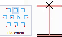
Equivalent illustration of
Placement Point options
The active placement point is marked with an arrow.
- Local Y Offset —
Used to modify the physical member's placement points in the Y axis direction.
- Local Z Offset —
Used to modify the physical member's placement points in the Z axis direction.
- Rotation Angle —
Used to modify the selected structural member or members by either entering a
new angle or interactively with data points.
- Interactive –
Modifies the rotation angle by entering a data point to spin members about
their member line axes as the cursor moves around the screen.
- Mirror — When on,
constructs an identical member type of the selected structural member or
members, but in a mirror-image/flipped orientation.
|
| Data tab
|
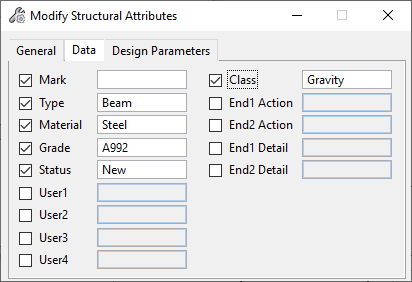
Contains controls for modifying the selected member or
members Structural Data attributes such as Structural type, class, material
grade as well as user defined attributes.
- Mark — Used to
enter a new identification mark for the selected structural member or members
(for instance, C1 for beam, B1 for beam).
- Type — Used to
enter a new Structural member type attribute for the selected structural member
or members (for instance, Beam, Column, Deck).
- Material — Used to
enter a new material attribute for the selected structural member or members
(for instance, Steel, Concrete, Timber).
- Grade — Used to
enter a new grade attribute for the material type of the selected structural
member or members (for instance, A36 for Steel, 4000psi for Concrete).
- Status — Used to
enter a new status for the selected structural member or members (for instance,
New or Old)
- User1–4 — Used to
modify the four available user definable Structural attributes for the selected
structural member or members. The reactions are used to identify or translate
member data with external applications.
- Class — Used to
enter a new class or component order for the selected structural member or
members (for instance, Primary, Secondary, Framing)
- End1/End2 Action —
Used to enter new end reactions for each end of the selected structural member
or members (for instance, 12K)
- End1/End2 Detail —
Used to enter new end details for each end of the selected structural member or
members (for instance, Type I, Type II)
|
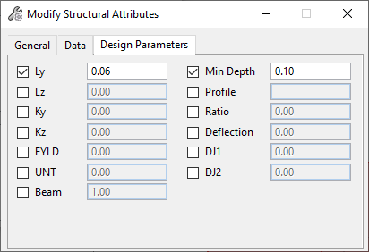
| Design Parameters tab
|
Contains controls for modifying the selected member or
members Design Parameters attributes before exporting to
STAAD.Pro via ISM. The specific design
parameters are dependent on which design code or standard is chosen. When a
design code is chosen, the associated parameters are initialized with default
values.
|