| AHU Builder menu bar
|
Task menus are provided to manage the AHU library and
the AHUs within the library.
 — Creates a new AHU library. — Creates a new AHU library.
Clicking
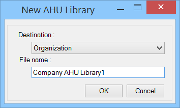
New Library opens the
New AHU Library dialog where you can
define the name for the AHU library in one of the destinations.
- Destination —
Allows selecting destination folder of the AHU library path.
Available options are:
- Organization
— The default library path where a series of AHUs that are supplied with the
application are stored in a library named
BentleyAHULibrary. The
organization domain path is selected for AHU Library for AHUs that need to be
shared across worksets within the organization.
- Workspace —
Assigns project AHU Library path to active user groups designated by active
wokspace.
- Workset —
Designates project AHU Library path where AHU scope is confined to active
workset.
Both destinations can also store user created AHUs.
Note: The
user privilege of accessing the
Organization destination to
create new library file is managed by the administrator in the configurations
settings (and network/file permissions to the user).
- File Name —
Enter the name of new AHU Library to be created in the given destination.
You can browse in the dialog to set a desired path for
storing the AHU libraries, If required.
Note: This
library path (set by
BMECH_AHUBUILDER_CATALOGS_PATH) is included in the
DG_CATALOGS_PATH configuration
variable.
While creating a new library, the sample.xml template
located in the path set by variable
BMECH_AHUBUILDER_TEMPLATE_FILEPATH is used to create a
file node.
 - Loads an AHU library. - Loads an AHU library.
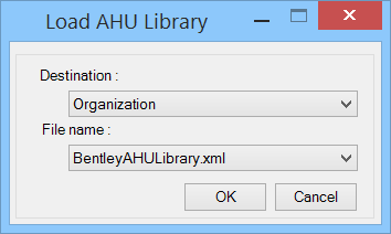
Clicking
Load Library opens the
Load AHU Library dialog where you
can select an existing AHU library file containing AHU configurations.
- Destination —
Allows selecting destination folder of the AHU library path.
Available options are:
- Organization
— The default library path where the default
BentleyAHULibrary supplied
with the application is stored. Select organization domain path for AHUs that
need to be shared across worksets (projects) within the organization.
- Workspace —
Assigns project AHU Library path to active user groups designated by active
wokspace.
- Workset —
Designates project AHU Library path where AHU scope is kept limited to active
workset.
You can also load user defined AHU Libraries stored in
the above destinations.
- File Name —
Select the name of a desired AHU Library available at destination to open in
the AHU Explorer.
Multiple libraries can be loaded in the AHU Explorer.
 — Unloads a selected AHU library.
Enabled when a library is selected. — Unloads a selected AHU library.
Enabled when a library is selected.
Clicking
Unload Library
unloads the selected library from AHU Explorer.
 — Copies data of currently
selected AHU in the clipboard. — Copies data of currently
selected AHU in the clipboard.
 — Pastes a copy of selected
configuration under current path of AHU Configuration. This is helpful when a
desired AHU could be used as a master across multiple libraries. — Pastes a copy of selected
configuration under current path of AHU Configuration. This is helpful when a
desired AHU could be used as a master across multiple libraries.
 — Creates a new AHU
configuration. — Creates a new AHU
configuration.
Clicking
Create AHU while a valid AHU Library
(file node) is selected, populates standard modules tree in the
Available Modules window in the
explorer lists.
 — Saves AHU configurations to
active library. — Saves AHU configurations to
active library.
Clicking
Save saves the current
configurations in AHU library.
An AHU needs to have at least a module created and
connections added before saving the configuration. The configuration data gets
saved in the XML after doing DataGroup refresh and create the AHU as a
component to be placed.
 — Places the active AHU in the
model. — Places the active AHU in the
model.
Clicking
Place AHU places currently
configured AHU in the drawing and brings control to the AHU Placement dialog.
The last placed AHU will be current and highlighted in the AHU List in the AHU
Placement dialog.
When cursor is moved in the view, the
Place Component dialog assists further settings like
placement justification, before placing the AHU. Such AHUs will have the
properties as designed in the AHU builder.
|
| AHU Explorer
|
Lists the library paths of AHU configurations being
saved. AHU Explorer will have those AHU Libraries earlier loaded in the AHU
Placement.
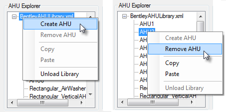
Right-click
menus in AHU Explorer
Note: For a
selected Library file node the Create AHU and Unload Library menus are enabled;
whereas the Edit, Remove and Copy menus are enabled when an AHU Configuration
is highlighted.
The right-click menu options are:
- For a selected
library path
- For a selected AHU
- Remove AHU — Removes the highlighted AHU permanently from
the AHU library, after confirming.
- Copy — Copies currently highlighted AHU configuration.
- Paste — Enabled when Copy command is activated; the paste
command adds a "Copy-" of selected configuration under
current AHU Configuration.
|
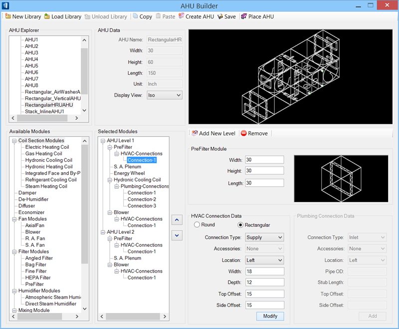
| AHU Data
|
Defines configuration name, displays the dimension
and allow to set display view to preview AHU in the preview window.
- AHU Name — Displays
default configuration name as
NEWAHU. The default name string can
be modified by overwriting.
- Width — Displays standard width of the AHU.
- Height — Displays standard height of the AHU.
- Length — Displays the overall length of the AHU assembly.
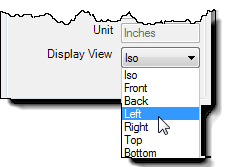
- Unit — Displays the system unit; "Inches" in case of
Imperial.
- Display View — Sets the orientation to view AHU assembly
displays in the AHU preview window.
Besides default Iso you can set
the display view to other to one of six sides too.
|
| AHU Preview window
|
Displays the geometrical view of the AHU assembly.
This includes all the modules built in the current AHU configuration.
|
| Available Modules
|
Lists the tree of various modules available for
building an AHU. The list populates standard modules data defined in the
AHUModuleData.xml file located in the path set by variable
BMECH_AHUBUILDER_DATA_FILE. Double
clicking a module gets added to the active level node in the Selected Modules
list . You can also drag a module and drop it in an AHU Level in the Selected
Modules list. Such modules would form part of current AHU configuration.
|
| Selected Modules List
|
Lists the tree of Selected Modules and Levels the
units being configured with. Initially when Creating AHU the Selected Modules
list provides only Level 1 branch. Level 1 being the base, successive levels
(usually 2 levels in horizontal mount) and modules are stacked on it. The level
determines the positioning of the module in the stacked AHUs. Double clicking
or selecting and dragging a module from the tree in the AHU Explorer lower
window into the Selected Modules list expands the Selected Modules. Selected
module is appended under the active level. You can then manipulate the order of
modules and connections to each module.
The right-click menus function in the context with
the highlighted tree element:
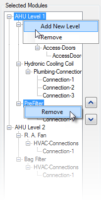
- For a selected AHU
Level
- Add New Level — The
menu is enabled when a level element is
selected. It adds a next higher level in the module list tree. Existing level
needs to have at least a module in it.
- Remove
— The
menu on a selected level prompts a
confirmation warning dialog. It removes the highlighted level and associated
modules with in it and renumbers the level by assigning the next higher number
to it.
- For a selected
Module/Connection
- Remove — The
menu is enabled when a module (or a
connection/accessory) in the list is selected. Selecting Remove menu pops up
confirmation warning dialog. It removes the highlighted module/connection from
the tree. The only (one) module in a (lower) level can not be removed, as
intermediate level cannot have zero modules; rather you can Remove the Level
with that module.
- The Move
Up and the Move
Down buttons move a highlighted module a
position up or down in the module list within current level, eventually shift
the module in the left or right in the AHU preview. The effect is also
reflected in the AHU Preview window.
|
| Module Menubar
|
Task menus are provided to manage the modules and
levels in the Selected Modules list.
 — Adds a next higher level in the
Selected Modules list tree. This is similar to the
menu in the Selected Modules list. — Adds a next higher level in the
Selected Modules list tree. This is similar to the
menu in the Selected Modules list.
 — Removes the selected
Level/Module/Connection or Accessory element from the Selected Modules list
after confirming a warning message. — Removes the selected
Level/Module/Connection or Accessory element from the Selected Modules list
after confirming a warning message.
When a level node is selected, the level along
with its associated modules (and connections) are removed from the Selected
Modules list. When a module or a connection (or accessory) is selected, the
selected module along with its associated connections (and accessories) are
removed. When a connection or accessory is selected, tit is removed.
This is similar to the
menu on the Level/Module/Connection or
Accessory element in the Selected Modules list.
|
| <Mixed Mode> Module
|
Defines dimension properties for
the module being added.
- Width / Height / Length — Define dimension of the module.
The default values can be altered to set required ones.
Note: The "Mixed
Mode" heading gets replaced with the name of the module being added or
highlighted in the Selected Modules list.
|
| Module Preview window
|
Displays the geometry of the module highlighted in
the module list. This is the preview of the cell symbol associated with the
module.
|
| HVAC Connection [Accessory] Data
|
Used to add connections to the selected module. The
HVAC Connection data defines HVAC connection details.
- Round / Rectangular — Determine the shape of the HVAC
module connection.
- Connection Type — Defines the type of connection. The pull
down menu lists connection types available in the selected module.
- Accessories — Defines accessory, such as access door, hood
etc., as required to the module.
Note: The
heading to this settings group changes dynamically when an accessory is
selected. For example, selecting Hood in place of None changes the heading from
HVAC Connection Data to
Hood Data. This is true in Plumbing
Connection Data settings too.
- Location — Determines the side of the module to place the
connection. The pull down menu lists all possible side for placing the
connection. A side on HVAC module can have one connection each.
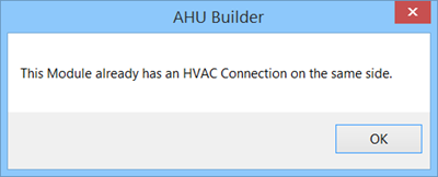
Warning messages prompt if you try to add
connections that conflict the design, for example:
- Depth — Defines the depth dimension of the connection.
- Diameter — Defines the diameter, for a
Round connection.
- Top Offset — Sets offset to the connection from the top of
the module to the center of the connection.
- Side Offset — Sets offset to the connection from the side of
the module to the center of the connection.
- Add/Modify — Clicking
Add adds the connection/accessory to
the module.
The connections added for a given module get
listed in the Current AHU Module List tree, grouped separately under HVAC
Connections and Plumbing Connections. The subsequent connections are numbered
"Connection-1", "Connection-2" etc. Selecting a connection in the module list,
turns the Add button to Modify, allowing altering connection details. This is
true for accessories too. You can repeat adding multiple connections as
required for the module.
|
| Plumbing Connection [Accessory] Data
|
Used to add connections to the selected module. The
Plumbing Connection data defines Plumbing connection details.
- Connection Type — Defines the type of connection. The pull
down menu lists connection types available in the selected module.
- Accessories — Defines accessory, such as access door, as
required to the module.
- Location - Determines the side of the module to place the
connection. The pull down menu lists all possible side for placing the
connection. A side on plumbing module can have multiple plumbing connections at
different offsets.
- Pipe OD — Sets the outer diameter of the plumbing
connection.
- Stub Length — Sets the length of the stub outlet.
- Top Offset — Sets offset to the connection from the top of
the module to the center of the connection.
- Side Offset — Sets offset to the connection from the side of
the module to the center of the connection.
- Add/Modify — Clicking
Add adds the connection/accessory in
the module.
You can repeat adding multiple connections as
required for the module. For example, Gas Heating Coil needs defining two
connections: (1) Gas In and (2) Gas Out; whereas Steam Heating coil will need
three connections: (1) Steam In, (2) Condensate Out and (3) Drain.
|
 (Edit AHU tool) in the
AHU
Placement dialog toolbar is accessed. (The AHU Placement dialog is
invoked via the AHU Builder tool from
(Edit AHU tool) in the
AHU
Placement dialog toolbar is accessed. (The AHU Placement dialog is
invoked via the AHU Builder tool from