Roofs
 Used to create and manage roof
designs which are then associated to floors in the project. The Roofs
dialog is the entry point into roof design, enabling the other
Roofs tab tools.
Used to create and manage roof
designs which are then associated to floors in the project. The Roofs
dialog is the entry point into roof design, enabling the other
Roofs tab tools.
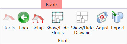
There is no limit to the number of roof designs your project can have. Each roof design has a separate object in the OpenBuildings Energy Simulator Project Tree hierarchy containing its own sub structure. The Roofs dialog is mainly used for creating new roof definitions, associating them to floors, and to initiate the roof design tools. Designing detailed roofs (roof physical geometry) requires additional steps using the roof design tools in the Roofs the Create Roof Element and the Modify Roof Element ribbon groups.
| Setting | Description | ||||||||||||||
|---|---|---|---|---|---|---|---|---|---|---|---|---|---|---|---|
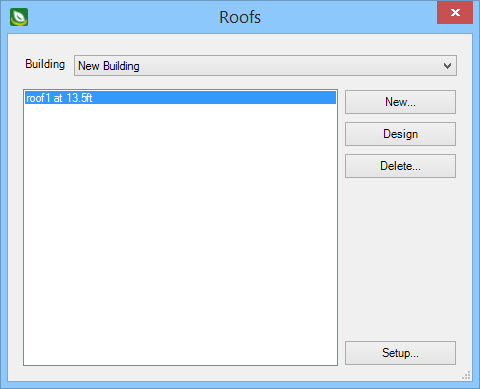
| Building | Lists the buildings on the project site. Roof designs associated with the buildings selected from the drop-down list are listed. | ||||||||||||||
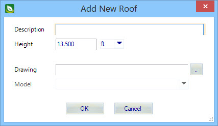
| New | Used to create a new roof model. Clicking
New opens the Add New Roof dialog, where the
new roof design is specified.
|
||||||||||||||
| Design | Makes the selected roof design active (opens the DGN model), and enables the roof design tools on the Roofs tab. | ||||||||||||||
| Delete | Deletes the selected roof. This deletes the graphics from the building model, restores all room surfaces that were changed when the deleted roof object was added, and removes the roof object from the OpenBuildings Energy Simulator Project Tree. | ||||||||||||||
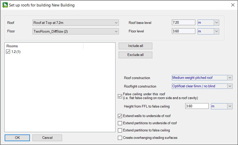
| Setup | Used to associate completed roof designs to floors existing in the project building or buildings. Clicking Setup opens the Set up roofs for building dialog (see Setup (Roof) ). |