Resize System - walk through Duct Sizing
-
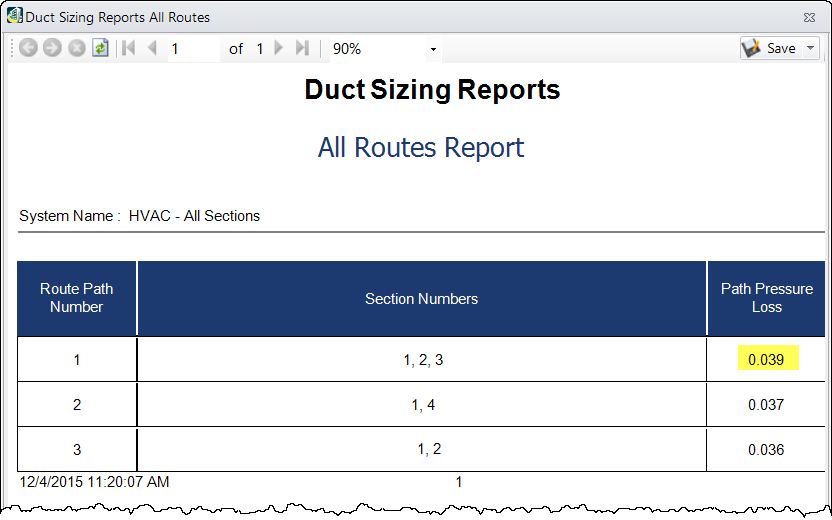
Run the option.
The Duct Sizing Reports All Routes report window opens listing all paths in the route and their pressure loss values in ascending order.
-
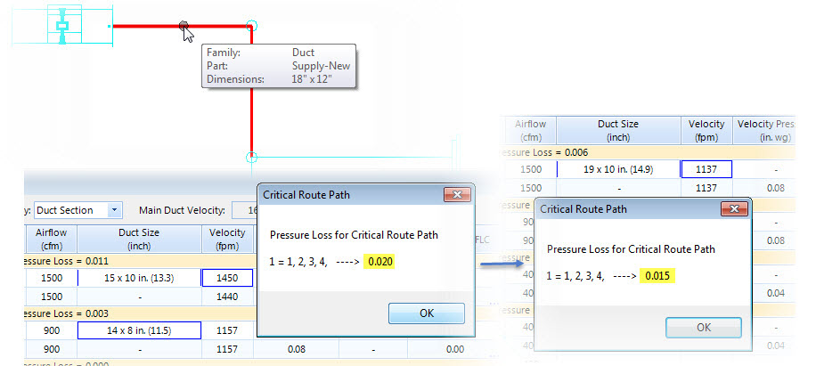
Analyse the Duct Sections in critical path. You may pick alternate duct size from the pull down list that smoothen the flow, Lock one of the values of Duct Size or Velocity or Pressure as allowed by the component in the design. You can always use the flyover hint to compare size in design to decide best match from alternates.
The altered values are to intent reducing pressure loss in the section and equalize the pressure across all section.
-
Recalculate and observe critical path status. When ducts are set for desired values you can walk through Fittings.
Fittings category may have more than one duct component, and analysed further in the Fittings Loss Coefficient table.
-
Double click in the Summary of FLC column.
The Fitting Loss Coefficient Summary dialog opens listing all sections and type of fittings in it.
-
Observe the loss coefficient and reset the values and/or add override, as required. Apply/reassign correct ASHRAE fittings by selecting a valid one from the tree view list.
This is done to components that will have improved performance and grade in design, e.g. added insulation lining to a duct section, using damper to limit velocity etc.
- For fittings assigned ASHRAE Fitting nos., will have standard loss coefficient values as published in the ASHRAE table. You will see a standard Loss Coefficient value assigned to each fitting. Looking at the values derived internally by the parameters (say, for a given r/D, for an elbow, or Qs/Qc for takeoff fittings) in case of Node-Branch, you may alter their Loss Coefficient overrides and set correction factor value to derive a minimal loss.
-
The default correction factor value for ducts and openings set to 1.0, however can be altered to expect desired pressure loss in the section.
Setting override suppresses the correction factor or loss value for the fitting.
Values set in FLC Summary table will also reflect in Duct Sizing table.
-
Switch to Duct Sizing summary and repeat the Calculate.
Repeat the steps of calibrating loss and coefficient values for next critical path until all sections are balanced for constant pressure loss.