Graphic Designer tab
Used to create new HVAC systems and sub-systems by dragging and dropping objects and components from the Designer Toolbox on to the Graphic Designer tab’s design area and making the necessary connections by drawing connection lines between the various component nodes.
The Graphic Designer tab contains controls used to create HVAC systems, HVAC subsystems and compound HVAC components. Design by searching for and selecting base HVAC components, compound HVAC components, HVAC subsystems, and HVAC systems from a database of EnergyPlus design objects from the Graphic Designer tab companion Designer Toolbox. Then using a drag and drop operation, moving them into the Graphic Designer tab design area, followed by making connections between their connection nodes.
| Setting | Description |
|---|---|
| Toolbar | Located at the top of the Graphic
Designer tab, the toolbar contains tools used to navigate through and
manipulate the display objects on the Graphic
Designer tab. The icons contained in this toolbar are:
|
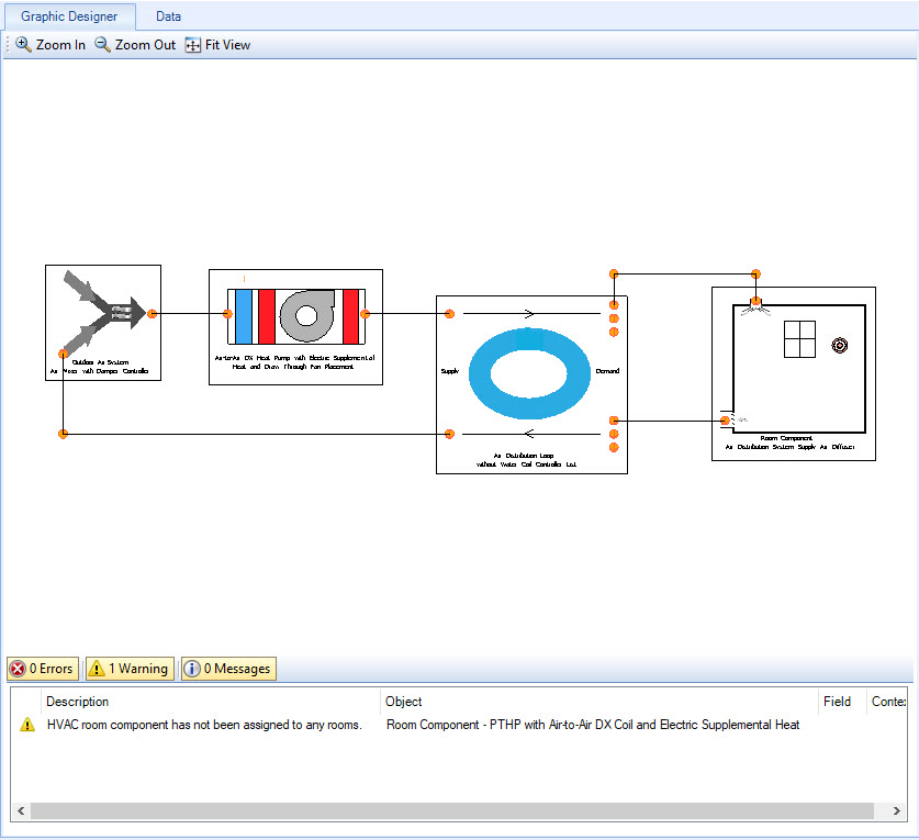
| Design area | This is the main area of the Graphic Designer tab where most of the design work is completed. When systems, subsystems are selected from the HVAC Systems tab, their diagrams are displayed in the design area ready. |
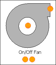
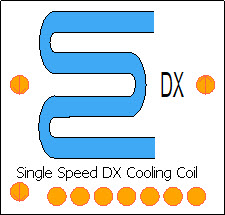
| Icons | HVAC Systems, HVAC subsystems, compound HVAC components and base HVAC components are represented in the diagrams with descriptive icons. For instance, a fan component is represented by an icon that looks like a fan. |
| Nodes | Applicable HVAC Systems, HVAC subsystems, compound HVAC components and base HVAC components have orange circular elements which represent the various types of connection nodes. For instance, a cooling DX coil’s inlet and outlet nodes (top left, top right) as well as nodes for performance curves (bottom). These are connected to nodes on other component icons. |
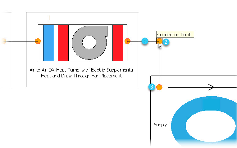
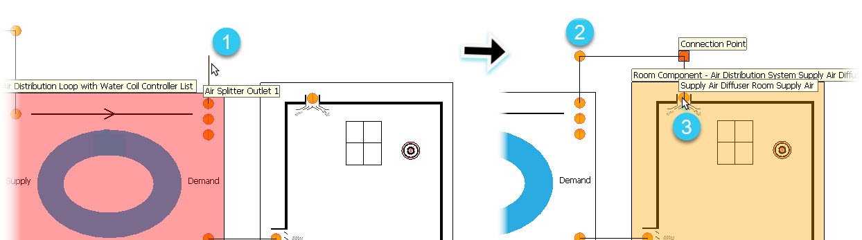
| Connection Lines | Connections are displayed with connection lines (1) and connection points (2) extending between the nodes (3). |
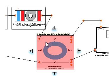
| Connections maintained | Connection lines remain connected to connection points and nodes when connected components are moved. |
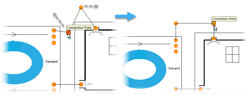
| Drawing connections | Connection lines are drawn by entering data points.
The first data point is entered on the starting node (1). Additional data
points can place connection points (data point is entered away from components)
to circumvent other objects (2). The last data point is entered on another
node, making the connection (3).
Note: Errors
associated with the components prior to being connected, are removed from the
Notifications
panel when connections are successfully made.
|
| Manipulating connections | Connection lines can then be rearranged by moving connection points. This straightens the lines and makes the schematic look neater. |
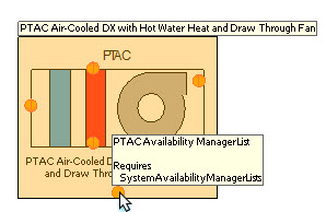
| Flyover help for connections | Connection nodes have flyover help. Position the pointer over a connection node, and the flyover help appears. For instance, the required object type is listed At the bottom of the flyover help. |
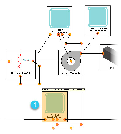
| Compatibility check for connections | Connection nodes are automatically validated as the connections are created. That is, only those components that are compatible with the component node being connected are highlighted (1). This functionality assists with making connections. Incompatible connections are not allowed. |
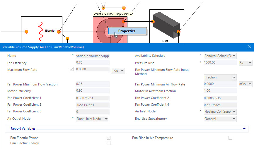
| Pop-up menus | Components can be queried by right clicking to open their pop-up menus Right clicking in an empty region of the Graphic Designer tab opens the active system pop-up menu. Connection lines and connection points also have pop-up menus. The options are: |
| Component properties help | Components vary greatly in their properties. EnergyPlus, where the components originate, provides a comprehensive listing of all HVAC objects and their properties. Properties number in the thousands. Detailed descriptions can be found on the EnergyPlus Input/Output Reference guide. |