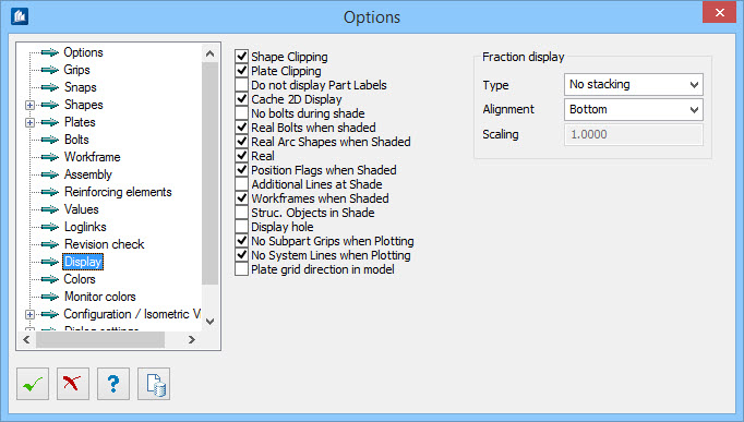
| Shape Clipping
|
The active UCS plane (top view) displays the
cross-section of the object tapered to it theoretically. This option should be
turned on.
When this option is switched off, you do not get a
correct cross-section top view of an object if it starts below and ends above
sectional plane.
|
| Plate Clipping
|
This option is identical with
Shape Clipping, but it is only valid for
plates.
|
| Do no display Part Labels
|
Any shape labeling inserted into the model is hidden
if the function Hide / Shade is selected.
|
| Cache 2D Display
|
The result of all line calculations effected by the
volume modeler (e.g. at a 2D-depiction, object snap, etc) is written into an
intermediate storage. A new calculation is only made in case of modifications.
Thus the processing speed for the determination of
AutoCAD®
- object snap-points especially in case of
complex construction groups is considerably increased.
|
| No Bolts during shade
|
Bolts are not displayed when the function Hide /
Shade is selected.
|
| Real Bolts when shaded
|
Bolts are displayed as real objects when the
function Hide/Shade is selected. This option should be turned on during
normal operation.
|
| Real Arc Shapes when shaded
|
Curved shapes (arcs) are displayed as real objects
when the function Hide/Shade is selected. This option should be turned on
during normal operation
|
| Real
|
Reinforcement elements will be shapes even in
wireframe display mode.
|
| Position Flags at Shaded
|
All position flags placed in the model will not be
hidden when the function Hide/Shade is selected.
|
| Additional Lines at Shade
|
All lines in the model, like centerlines, gravity
lines or other construction lines will not be hidden when the function
Hide/Shade is selected.
|
| Workframes when Shaded
|
All work frames within the model will not be hidden
when the function Hide/Shade is selected.
|
| Struct. Objects in Shade
|
Structural objects are displayed in render display,
when the function ‘Hide/Shade’ is selected.
|
| Display Hole
|
Holes are always displayed as polygons consisting of
lines, even if it is a matter of real holes in ACIS-objects.
|
| No Subpart Grips when Plotting
|
There is no output of subpart
handles at plotting.
|
| No System Lines when Plotting
|
There is no output of system lines of structural
elements (container graphics, e.g. stairs, purlins, handrails etc.) at
plotting.
|
| Plate grid direction in model
|
In plates with grids, additionally displays the main
grid direction.
|
| Fraction Type
|
Sets the type of a stacked fraction. If an annotation
text is related to a dimension style (e.g. hole diameter), the fraction
settings are used from that style. Here you can set either horizontal, diagonal
stacking or no stacking.
- No
Stacking – used as default when an old drawing is loaded. There are
no stacked fractions visible until that style will be changed (requires an
element update) or some new elements will be created.
- Horizontal
Stacking – Aligns the stacked fraction horizontal. (e.g. 0
1–4').
- Diagonal
Stacking – When set, stacks the fractions diagonally. (e.g. 0¼').
Text display resulting from element property data (e.g. shape
length, is shown as ‘10:6 3/8’) could be different regarding how this text have
been created. If it consists of basic
MicroStation text that is already part of the
DGN nothing will change. However, when a text is embedded into a
OpenBuildings Designer element that is
calculated and drawn on runtime, this text display will change to a better
display style. It will happen when the element display is updated and includes
fraction stacking too.
|
| Alignment
|
Sets the alignment of the stacked fraction of
selected style annotation. The alignment influence how to the fraction display
be aligned.
- Bottom – Aligns
in the annotation element at bottom.
- Center – Aligns
in the annotation element in the center.
- Top – Aligns in
the annotation element at top.
|
| Scaling
|
Indicates the text size scaling of stacked fraction.
The scaling values are set to 1.0 (of text size) by default.
|