Floor Selector
 Used to select floors and
associated floor reference planes, and to make them active for modeling and
placing graphics. Floor Selector also sets active floors among multiple
Buildings and has integrated tools interfacing with
Grid Systems. When the Floor Selector tool is selected, the Floor
Selector interface opens and is docked by default along the bottom edge of the
application window. It can also be floated or docked along the top edge of the
application window, or closed during workflow. The Floor Selector can remain
docked. When docked, choose a floor or floor reference plane from the pull down
option menu and double click to set it active.
Used to select floors and
associated floor reference planes, and to make them active for modeling and
placing graphics. Floor Selector also sets active floors among multiple
Buildings and has integrated tools interfacing with
Grid Systems. When the Floor Selector tool is selected, the Floor
Selector interface opens and is docked by default along the bottom edge of the
application window. It can also be floated or docked along the top edge of the
application window, or closed during workflow. The Floor Selector can remain
docked. When docked, choose a floor or floor reference plane from the pull down
option menu and double click to set it active.

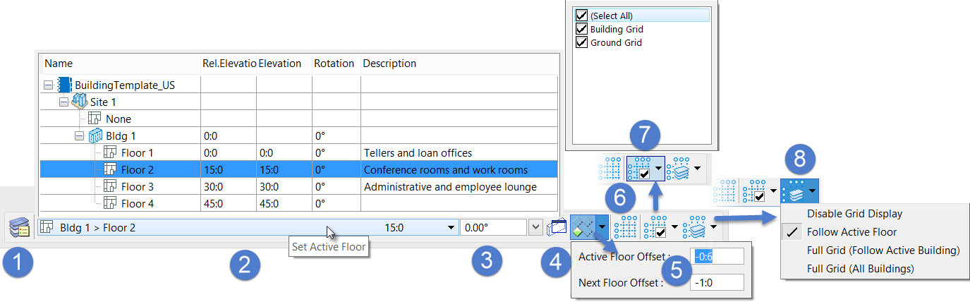
- Floor Manager
- Set Active Floor
- Set ACS Rotation
- Align View with ACS
- Isolate Active Floor
- Grid Systems Manager
- Set Active Grids
- Grid Model Display Options
Options and Settings Illustrated
| Setting | Description |
|---|---|
 (Floor Manager) (Floor Manager)
|
Opens Floor Manager, where buildings, building floors and floor groups be create and managed including the sub-floor reference planes, and floor information for projects. Floor Manager creates an Auxiliary Coordinate System (ACS) that looks and behaves like a system of floors in a building. Once floors and floor reference planes are created, the Floor Selector tool is used activate specific floors or reference planes. When active, all data points and tentative snap points are forced to the Z elevation of that floor. |
| Set Active Floor | Clicking here displays a hierarchical list of all
selectable building and floors, and displays the active Building, Floor and
Floor Elevation when collapsed. The list contains all floors, associated floor
reference planes, and typical floors and typical floor groups that are
established in the Master Floor File
(BB_FloorMaster.dgnlib). Floor Selector can be used to
create drawing definitions based on templates delivered in the Master Floor
File. The Floor list box is also used to select floors and associated floor
reference planes; to make them active for modeling and placing graphics. The
highlighted floor in the list is set as active floor. Floors and their
reference planes are displayed by rows in expandable/collapsible directories.
Information about each floor definition is displayed in a series of columns
that can be re-sized. The list box includes the following columns.
Note: Since floor
reference planes are always relative to the floors that own them, Relative
Elevations for floor reference planes never change, regardless of the active
Floor Options mode. For example, the window sill reference plane height for a
floor generally remains the same relative to that floor, regardless of a change
in floor elevation within the building, or a change in the building elevation
to topography.
Note: The Floor
Management System defines the cut location and cut view using the Distance and
Orientation option for Drawing Definitions.
Tip: Relative elevations are
calculated using base elevation settings in conjunction with real world
elevations. Generally, relative elevations can be used to compensate for
differences in elevation such as topographic elevation between building floors
or between buildings. The following examples are offered to clarify this.
|
| Set ACS Rotation | Used to rotate the ACS and the AccuDraw compass simultaneously. You can enter a rotation angle or select a rotation by clicking the down arrow, and the active ACS rotates about the Z axis by the specified angle. |
 Align View with ACS Align View with ACS
|
Used to rotate a view to align it with the active ACS plane. The view is rotated so that its X, Y, and Z axes are aligned with the X, Y, and Z axes of the active ACS plane. |
 Isolate Active Floor Isolate Active Floor
|
Creates a displayset in the active view of all those
elements within the active Floor range allowing you to easier navigation and
investigation of complex models. Even elements that extend through this range
are included. The pull-down options manipulate the active Floor's range
affecting the inclusion or exclusion (in the displayset) of elements in
adjacent Floors.
|
 Grid Systems Manager Grid Systems Manager
|
Provides quick access to the Grid Systems Manager dialog which is used to set the shape, size, placement, and appearance of all elements and components contained in a grid system. |
 Set Active Grids Set Active Grids
|
Activates grids by checking them from the pull-down list. The selected grids are made active and are available to view and dynamically display. The grids in the list are the current grid definitions available in the grid systems manager. |
 Grid Model Display Options Grid Model Display Options
|
Determines when and how the Dynamic Grids are
presented. One of these options is always set:
|