| Shapes tree
|
This list contains catalogs of shapes, each
containing special shape types. Use the tree controls -by expanding or
collapsing nodes to navigate into the catalogs.
|
| Right-click menus
|
- Partlist
Data – Opens the "Partlist
Data-<shapename>" dialog where the shape details including item number,
material, dimensions, and remarks are set.
- Display –
Displays the selected shape geometry at the origin in the current view.
- Rename – Allows
changing the name of the selected user shape.
- Create
Low/Normal/High Resolution – For selected weld shape opens Weld
Shapes dialog, and for selected I -Type Welded Shape opens Weld Shape I Type
dialog, respectively. Change menu changes the resolution.
- Create
Param User Shape – Opens Definition Parametric Shapes dialog where
based on basic polygon shapes the parametric user shapes are created.
- Delete –
Removes the selected user shape from the shape tree.
|
 Used to add special shapes to
your
Used to add special shapes to
your
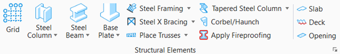
 Create User
Shape
Create User
Shape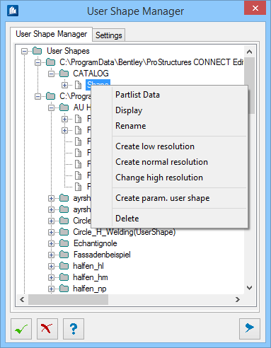
 OK
OK
 Cancel
 Help
Help

 Show /Hide
Preview
Show /Hide
Preview