Independent Annotations
Independent Grid Annotation
Allows you to manipulate individual grid lines in the 2D drawing view.
-
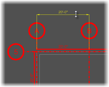
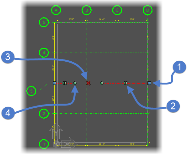
Grid Lines
- Move End — Placing the cursor on the grid line displays the Modify Grid Line handles at the ends, selecting one and dragging it moves the grid line in the direction it is dragged.
- Create Gap — Placing the cursor on the grid line run displays it as Create Gap handle at the midpoint, and clicking it creates a Gap of width defined by the datapoint.
- Delete Gap — Clicking on the Remove Gap handle undoes the Gap by joining the grid line elements into one.
- Move Gap (Start/End) — Selecting and dragging the Move Gap handle at the start or at the end of the grid line segment, it moves the grid line element end point in the direction of dragging.
-
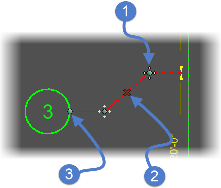
Grid Line Extensions
- Create Dogleg (Start/End) — When the grid line extension is selected, a Dogleg at the start of extension line and end dogleg at the end of extension line is seen. When selected one and dragged, the selected dogleg start/end is moved in the direction it is dragged.
- Delete Dogleg — Clicking on the cross marked handle seen in the middle of both doglegs undoes the dogleg on the grid line.
- Move Bubble — Selecting and dragging the Move Bubble handle moves the grid Label in the direction of dragging and displaces the grid line extension.
Independent Elevation Annotation
Grid systems located on floors create an annotation in elevation drawing views.
Elevated grid systems create an annotation in elevation
drawing views that displays floor elevation details defined in the default grid
template. You can manipulate elevation annotation by enabling and modifying
grid line.
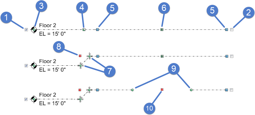
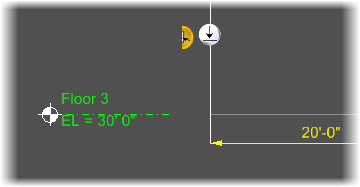
- Enable/Disable Elevation Label — When on, the elevation label is displayed. For instance, EL = 15' 0".
- Enable/Disable Grid Label — When on, the grid label is displayed. For instance, Floor 2.
- Modify Elevation Leader — Moves the elevation leader line endpoint attached to the elevation symbol. Movement is restricted to be collinear with the grid line.
- Create Leader Offset (dogleg) — Creates a diagonal line segment between the edit handle location and the point you select establishing a dogleg. The Create Leader Offset (dogleg) edit handle is then replaced by two Modify Leader Offset edit handles.
- Modify Grid Line — Moves the grid line endpoint. Movement is restricted to be collinear with the grid line.
- Create Gap — Breaks the grid line starting at the edit handle location and ending at the point you select. The Create Gap edit handle is then replaced by two Modify Gap edit handles.
- Modify Leader Offset — Moves the endpoints of the diagonal line segment forming the dogleg. Movement of the endpoint attached to the grid line is restricted to be collinear with the grid line.
- Remove Leader Offset — Deletes the diagonal line segment forming the dogleg, and moves the offset portion of the elevation leader line back inline with the grid line. The two Modify Leader Offset edit handles are replaced with the Create Leader Offset (dogleg) edit handle.
- Modify Gap - Moves the endpoints of breaks in the grid line. Movement is restricted to be collinear with the grid line.
- Remove Gap — Deletes breaks in grid lines. The two Modify Gap edit handles are replaced with the Create Gap edit handle