-
Next, Select
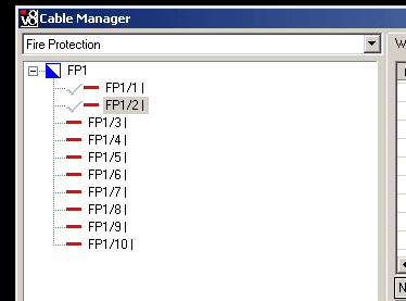
 (Cable Manager) tool.
Opens the Cable Manager dialog.
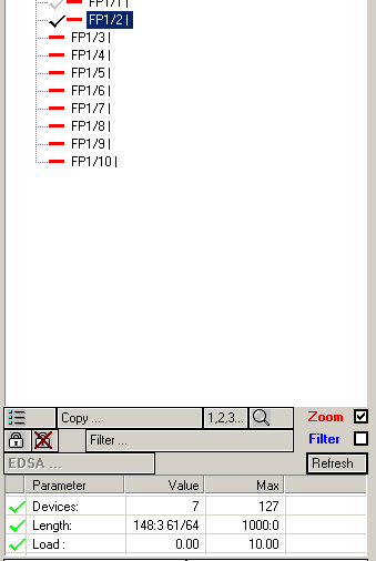
On the left side, the circuits FP1/1 and FP1/2 are marked, but greyed out. This indicates that these circuits are placed in another drawing / floorplan. It is not possible to access any information about circuits that are connected/placed in other drawings
(Cable Manager) tool.
Opens the Cable Manager dialog.
On the left side, the circuits FP1/1 and FP1/2 are marked, but greyed out. This indicates that these circuits are placed in another drawing / floorplan. It is not possible to access any information about circuits that are connected/placed in other drawings
-
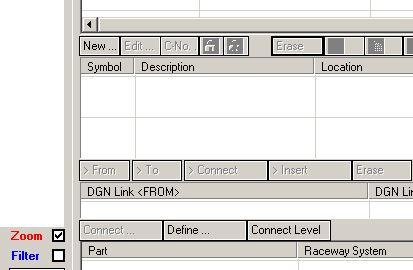
Next, click Connect Level.
This established the connection to the DGN Link matrix from the lower floor level.
-
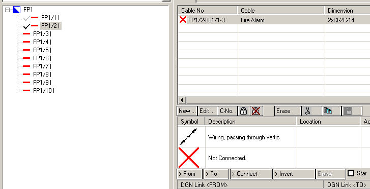
The Cable Manager connects to the lower floor level.
Notice that the circuit FP1/2 on the left is now activated.
-
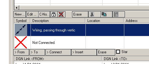
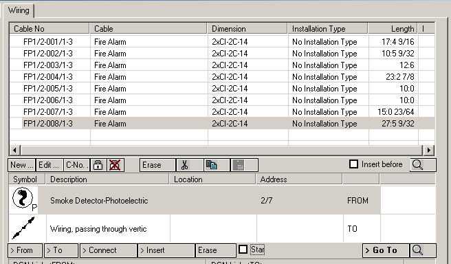
Select the DGN Link symbol in the list and then click > Connect below it.
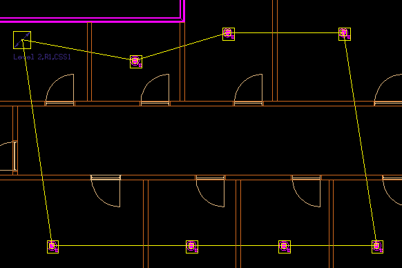
Then wire a loop in the drawing, starting and ending with the DGN Link symbol.
-
To check result, click
 on the Wiring Circuit panel in the left in Cable Manager.
Result/visualisation of loop in second floorplan.
on the Wiring Circuit panel in the left in Cable Manager.
Result/visualisation of loop in second floorplan.
-
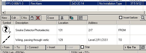
The Cable Manager also provides information about the number of devices in a circuit, it checks the maximum length of cables and load information. Select Line FP1/2 and then click on the "Refresh" button below it.
Note: Electrical discipline will not stop the you from exceeding maximum values.
Clicking "Refresh", Address information is visible for all devices/cable segments in circuit.