Setup Model Link Matrix
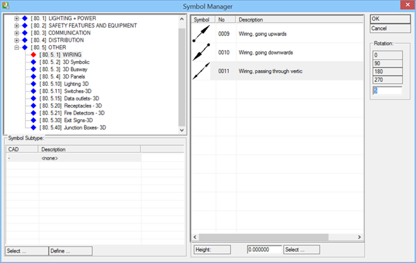
Next, insert a Model Link symbol into the drawing.
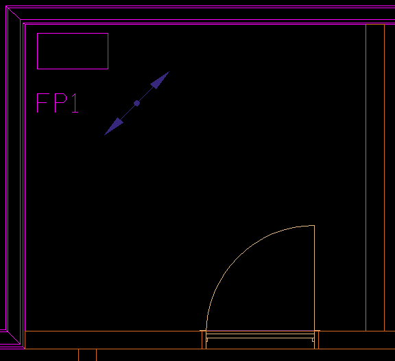
- Select the symbol "Wiring, passing through vertic" and set it's Height to 5:0.
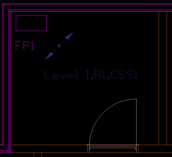
- Place symbol next to Distribution Panel in drawing. This marks the point where the cable will be routed through to the upper floor level and back.
-
Select
 ( Model
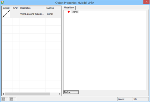
Link). Then click on the Model link symbol with datapoint.
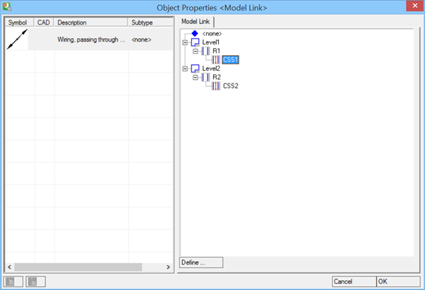
Opens the
Object Properties ‹Model Link› dialog.
The Model Link panel lists the link treeview.
( Model
Link). Then click on the Model link symbol with datapoint.
Opens the
Object Properties ‹Model Link› dialog.
The Model Link panel lists the link treeview.
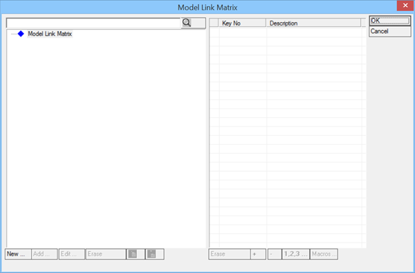
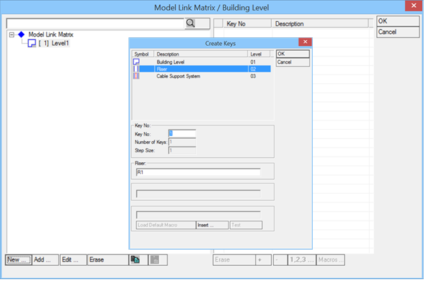
- Click Define. Opens the Model Link Matrix dialog.
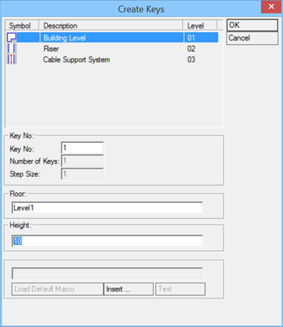
- Click New. Opens the Create Keys dialog. Enter Level 1 for Floor and 10 for Height and click OK to apply.
- Create tree of matrix elements in the Model Link Matrix / Building Level dialog:
- Now, copy-paste the matrix elements in the Model Link Matrix / Building Level dialog: The matrix element structure gets copied in the treeview.
-
Now, rename the matrix elements In the Model Link Matrix /
Building Level dialog:
- Select the [2] Level1 element and click Edit.
- The Building Level Properties dialog opens.
- Enter Level 2 in the Level field and set Height to 0.
- Click OK to apply.
- Return to the Model Link Matrix dialog.
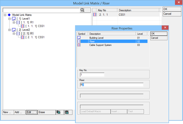
- Select the [2,1] R1 element and click Edit.
- The Riser Properties dialog opens.
- Change Riser field value to R2 and click OK.
- Return to the Model Link Matrix dialog.
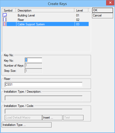
- Select the [2,1,] CSS1 element and click Edit.
- The Cable Support System Properties dialog opens.
- Change Riser field value to CSS2 and click OK.
- Return to the Model Link Matrix dialog. The structure changes as renamed.
- In the Object Properties ‹Model Link› dialog, highlight the entry CSS1 on the right panel and click OK. The label "Level 1,R1,CSS1" appears next to the link matrix symbol in the drawing.
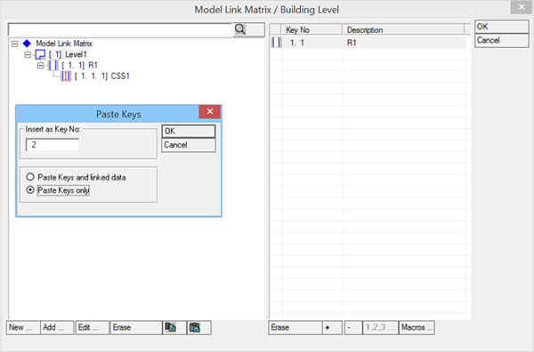
 to copy the structure to Windows
Clipboard.
to copy the structure to Windows
Clipboard.
 to copy the structure from
Windows Clipboard.
to copy the structure from
Windows Clipboard.