Structural, Parts
Contains controls that define the physical characteristics of a structural member upon placement. Settings include default section, placement point and local offsets.
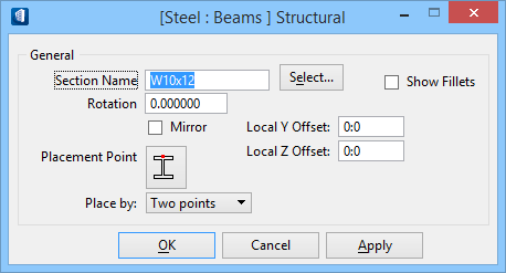
This Structural View menu item dialog is accessed by choosing Properties from the right-click pop-up menu in the list box, while the Parts View on Family/Part Editor is Structural.
| Setting | Description |
|---|---|
| Section Name | Displays the default structural section used by the part being defined. Key in the section name or click the Select button to browse in the Structural Sections dialog. |
| Select | Opens the Structural Sections dialog, listing industry standard section sizes. You may shorten the list using the Code and Type filters, and select a structural member's section from the listed section sizes. The selected section displays in the Section field. |
| Show Fillet | When on, fillets between member flanges and web are fully modeled and displayed. |
| Rotation | Defines a default angle of rotation about the member centroid upon placement. |
| Mirror | Indicates mirroring. When on, flips the flanges to the opposite direction. Applicable to members, such as angles, channels, or zees whose axis is asymmetrical about its Y axis. |
| Placement Point | Defines the location on the section to be used as the origin of the member upon placement. There are nine physical placement points and one theoretical centroid available. To alter the structural member's Placement Point, click on the icon to select one from the pop-up options:
|
| Place by | Sets the default placement method for a single member placement such as a column or beam.
|
| Local Y/Z offset | Sets the offset values that determine member placement dynamics and member positioning relative to local coordinates. It moves the physical member's placement away from the member line in the Y-/Z-axis direction. |
| OK | Accepts changes and dismisses the dialog. |
| Cancel | Discards changes and dismisses the dialog. |
| Apply | Applies changes without dismissing the dialog. |