OpenBuildings™ Designer Help

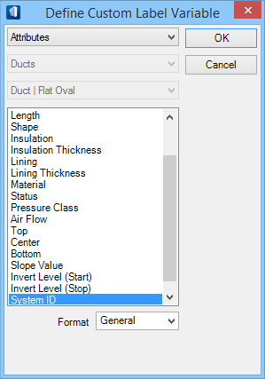
Define Custom Label Variable (Mechanical) dialog

Used to define the variables for your custom labels attributed to the selected Mechanical Rule.


This dialog appears when you are defining a custom label and you click Add Attributes in Attribute Label tab of Drawing Rule.
SettingDescription
Attributes/Datagroup Properties

Lists the Attribute properties; this is separated from DG Properties to filter only Mechanical Attributes. When set to DataGroup Properties, the following settings sort those properties in Ducts and Pipes fittings, that usually required to label.

Select the attribute that you want to add in the Label Format text field on the Labels tab for your custom label.
Ducts/Pipes When selected, lists DG properties filtered to only ducts or only pipes category.
  • For Ducts, the next filter lists Ducts in available shapes —rectangular, round, oval, and flexible ducts.
  • For Pipes, the next filter lists Pipes in available shapes —straight pipes, and flexible pipes.
Selecting one of these shapes for the fitting, accordingly the Datagroup properties list is sorted in alphabetical order that eases the selection of required property.

Create custom labels for information about fitting' DataGroup data. The DataGroup properties are distinguished by the bold headings representing the property schema types that are also found in the placement and modify tools.

Format Select the format for the attribute.
Values are:
  • General – Output the string attribute value as stored. For example, if you select Section Name, then Section Name will appear in the Label Format field and the section name will appear in your extracted drawing as your custom label.
  • Number – Output the attribute value as a number with the indicated number of decimal places.
  • Scientific – Output the attribute value as a number using scientific notation (E format) with the indicated number of decimal places.
  • Custom — Use a scripting program such as VBA, and function to format the text during drawing composition.
Key in fields Key in fields appear depending upon which format is selected
for Number and Scientific formats:
  • Decimal places – This text field appears when you select a format that will let you have decimal places in the value. It applies to Format values of Number and Scientific.
For Custom format:
  • Script Name – This text field appears when you select a format of Custom. Enter the name of the script for the program.
OK Closes the dialog, saving any changes you made to newly created variables. The value you have selected is automatically added to any existing values in the label Format field on the Attribute Labels tab for the custom label.

Example of a custom composite mechanical annotation

Generating Custom Compound annotation like the following style:


Where:
  • LD1, LD2 – indicate system ID,
  • DN65 – means the type and gauge
  • (1.75) – means the elevation of pipes
This is achieved by constructing the Format string, as below:
%SYSTEM_ID%DN%EndSpec1_2/End1/@diameter%(%BOTTOM%)
Meaning, the Format attributes need to be set as

Attribute < System ID> +"DN"+ DataGroup Properties | Pipes | Flex Pipes <End_Spec1_2End1/@diameter> Attribute <Bottom>

To get the above result, carry out the below steps in the Custom Level Variable dialog:
  1. First select the Attributes properties, and define the attribute in as System ID, and click OK.
  2. In the Format field, key in DN and click Add Attribute.
  3. Select DataGroup Properties attributes, followed by Pipes and Straight Pipes.
  4. In the properties list scroll and under the schema type End_Spec1_2(1 Connection: Round), select the End_Spec1_2End1/@diameter, and click OK.
  5. Again in the Format field key in the open parenthesis character "(", and click Add Attribute.
  6. Select Attributes properties attributes in the properties list, scroll and select Bottom, and click OK.
  7. In the Format field, key in the close parenthesis character ")".
  8. Click OK in the Drawing Rule dialog.
The Drawing rule updated in the Drawing Rule dialog will have the newly defined custom label variable attributed. When applied to the fittings in the drawing, here pipes will reflect the resultant labels as illustrated above.