To place a beam layout
To place a beam layout between pier lines, use the following procedure.
A beam layout is
used to specify the general girder geometry for a slab and girder bridge. This
procedure is used for concrete and steel girder bridges.
- Either
- (Optional) Type a Name for the beam layout in the Place Beam Layout tool settings dialog.
-
To specify the layout limits, do the following in the view window:
- data point on the first supportline to use as the start limit line
- data point on the second supportline to use as the end limit line
- data point a third time to accept
- (Optional)
Select a different
Alignment or
Aux Alignment if necessary:
To… Do the following… Select a different alignment Click Select and then data point on an alignment in the view window. Add an auxiliary alignment Click Add and then data point on an alignment in the view window. - Select the Placement Method: Simple or Continuous.
- Select the spans to which the current layout will apply.
- Type the Number of Beams in the span cross-section and click Apply.
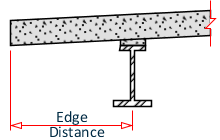
- Type the Edge Distance in the span cross-section and click Apply.
- (Optional) Specify the default parameters to use for all beams in the span:
- (Optional) You can manually edit most of the values of individual beams in the details table.
- Click Validate.
- Click Save.