If the interface dialog is available in the selected
import format, it can also contain a page for General Settings apart from the
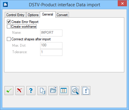
specific pages. This page is identical for all interfaces and permits settings
for the import process. Depending on the implementation degree of the
interface, it is possible that certain fields are not activated.
| Setting | Description |
|---|
| Create Error Report
|
Creates an error report during import and model
generation. You can see here which data are defective or which cannot be
evaluated by
OpenBridge Modeler.
If such an error report was created, you can
display it by clicking the
 (Error
Report) button in the dialog. (Error
Report) button in the dialog.
|
| Create Workframe
|
Creates a working area of 6 basic views with the
help of the outer dimensions of the imported model.
|
| Name:
|
Indicates the name of the working area. If it still
exists, the new views obtain the index "2".
|
| Connect shapes after import
|
When checked, connects continuous shape parts (bars)
to a common shape.
Only those shapes are connected which have the same
size and position, which are situated on a common axis and which don’t exceed a
preset distance of the end points.
|
| Max. Distance
|
Sets the maximum distance, which is allowed for the
end points to be connected to be recognized as continuous shape.
|
| Tolerance
|
Sets a tolerance for possible deviations of the
gusset coordinates.
This is reasonable when you import data of static
analysis programs as these are generating a system of bars from gusset to
gusset (e.g. plate connection) although in reality it is a continuous shape.
|
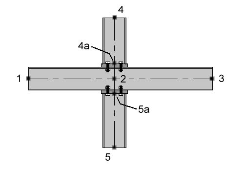
Connecting
Shapes
The static program transfers this system as 4 bars of
1-2, 2-3, 4-2 and 5-2. Four shapes are created first which are connected in the
way that there will be one remaining shape of 1-3 and one of 4-5.
Supposed the fact that bars of 1-2, 2-3, 4-4a and 5-5a
were transferred, the bars 4-4a and 5-5a would only be connected to a shape if
the distance of 4a to 5a was smaller than indicated in ‘Max. Distance’ input
field.