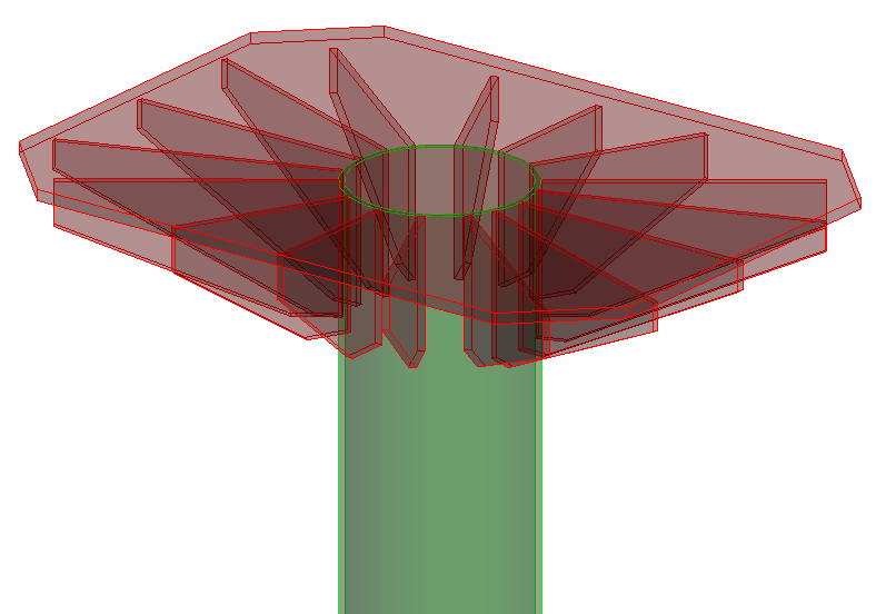
Single Frame Cap
 Used to parametrically create
stiffened cap plates, commonly used in electrical substations. Single frame
caps can be placed on any vertical, sloping, or skewed pipes or square,
rectangular, and circular hollow shapes.
Used to parametrically create
stiffened cap plates, commonly used in electrical substations. Single frame
caps can be placed on any vertical, sloping, or skewed pipes or square,
rectangular, and circular hollow shapes.

Top Cap Plate tab
Used to define the geometry of the top cap plate.

| Setting | Description |
|---|---|
| Rectangle | When on, the top plate corners are not chamfered. |
| Thickness | Sets the thickness of the plate. |
| Outer Length / Width | Sets the outside dimensions of the plate. Denoted with 1 and 2 in the diagram. |
| Inner Length / Width | Sets the dimensions between the chamfers of the plate. Denoted with 3 and 4 in the diagram. |
| Rotate | Specifies a rotation angle for the placement of the plate. |
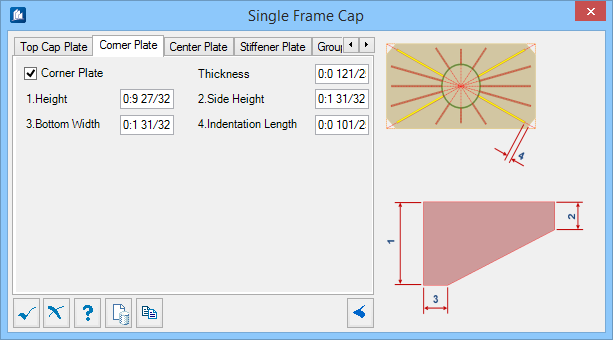
Corner Plate tab
Used to define the geometry of the corner stiffener plates. Illustrated with yellow color in the diagram.
| Setting | Description |
|---|---|
| Corner Plate | When on, the corner stiffener plates are included with the frame cap. |
| Thickness | Sets the thickness of the plate. |
| Height | Sets the height of the plate where it is attached to the frame. Denoted with 1 in the diagram. |
| Side Height | Sets the height of the plate at its outermost extent. Denoted with 2 in the diagram. |
| Bottom Width | Sets the width of the plate at the bottom. Denoted with 3 in the diagram. |
| Indentation Length | Sets an offset distance from the top cap plate chamfer (or corner) to the corner stiffener plates. Denoted with 4 in the diagram. |
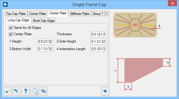
Center Plate tab
Used to define the geometry of the center stiffener plates both at the Long Cap Edge and Short Cap Edge. Illustrated with yellow color in the diagram.
| Setting | Description |
|---|---|
| Same for All Edges | When on, the parameters defined on the Long Cap Edge tab are applied to the Short Cap Edge tab. When off, you can set the Short Cap Edge parameters independently. |
| Center Plate | When on, the center stiffener plates are included with the frame cap. |
| Thickness | Sets the thickness of the plate. |
| Height | Sets the height of the plate where it is attached to the frame. Denoted with 1 in the diagram. |
| Side Height | Sets the height of the plate at its outermost extent. Denoted with 2 in the diagram. |
| Bottom Width | Sets the width of the plate at the bottom. Denoted with 3 in the diagram. |
| Indentation Length | Sets an offset distance from the top cap plate edge to the center stiffener plate(s). Denoted with 4 in the diagram. |
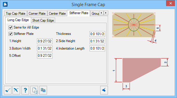
Stiffener Plate tab
Used to define the geometry of the intermediate stiffener plates both at the Long Cap Edge and Short Cap Edge. Illustrated with yellow color in the diagram.
| Setting | Description |
|---|---|
| Same for All Edges | When on, the parameters defined on the Long Cap Edge tab are applied to the Short Cap Edge tab. When off, you can set the Short Cap Edge parameters independently. |
| Stiffener Plate | When on, the intermediate stiffener plates are included with the frame cap. |
| Thickness | Sets the thickness of the plate. |
| Height | Sets the height of the plate where it is attached to the frame. Denoted with 1 in the diagram. |
| Side Height | Sets the height of the plate at its outermost extent. Denoted with 2 in the diagram. |
| Bottom Width | Sets the width of the plate at the bottom. Denoted with 3 in the diagram. |
| Indentation Length | Sets an offset distance from the top cap plate edge to the center stiffener plate(s). Denoted with 4 in the diagram. |
| Offset | Sets an offset distance from the center stiffener plate to the intermediate stiffener plate(s). Denoted with 5 in the diagram. |
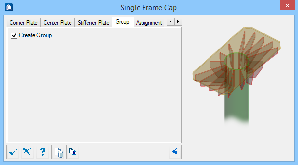
Group tab
Used to create a new OpenBridge Modeler group with the Substation Gallery objects.
| Setting | Description |
|---|---|
| Create Group | When on, you can select additional shapes. Separate single frame caps are created. |
Assignment tab
Used to assign elements in the connection to a material, display class, area class, part family, level, etc.

Dialog Controls
| Setting | Description |
|---|---|
 OK OK
|
Closes the dialog and save your changes. |
 Cancel Cancel
|
Closes the dialog without saving changes. |
 Help Help
|
Opens online help. |
 Template Template
|
Saves and retrieve (Using Templates) settings to be used on other projects. |
 Clone Clone
|
Shifts focus to the geometry, allowing cloning the current structural object (stair, frame, truss, etc.) properties to match one or more objects selected in the view. |
  Show /Hide
Preview Show /Hide
Preview
|
Opens or closes, respectively, a flyout panel to display an illustration based on the tool. |