| Length / Width
|
(Read Only fields). Display the length and the
width, respectively of the Brace Plate.
|
| Thickness
|
Sets the thickness of the Brace Plates.
|
| Left/Right
|
Determines the placement of the Brace Plates.
|
| Trans. Distance to Top/ Bot.
|
Sets the transverse distance from the center of the
hole to the top or to the bottom of the plate.
|
| Long. Dist. to Start
|
Sets the longitudinal distance from the start of the
plate to the center of the hole.
|
| Bolt to Notch Dist.
|
Sets the distance between the center of the hole to
the notch.
|
| Notch Depth.
|
Sets the depth of the notch.
|
| Notch Width
|
Sets the width of the notch.
|
| Insertion Gap
|
Sets the distance from the inner most point of the
notch to the start of the rod.
|
| Bevel
|
Sets the value for the bevel.
|
| Material
|
Selects the material to be used for the connection.
|
| Group
|
When checked, the entire connection, including the
connecting shape, is assigned to a construction group. If the shape is already
part of another component group, the connection will be assigned to the same
group.
|
| With Bolts
|
When checked, the bolts are also added to that
group.
|
| Shape Type
|
Selects the shape type to be used for the Rod Brace
connection.
|
| Shape Size
|
Selects the shape size to be used for the connection.
|
| Rod Length
|
(Read Only). Displays the length of the Rod.
|
| Bolt Type
|
Sets the type of bolt selected from the drop-down
list.
|
| Turn
|
When checked, the bolt direction is inverted.
|
| Diameter
|
Displays the diameter of the bolt. If two fields are
present, the left field represents the first selected plate while the right
field represents the second selected plate.(Read Only - the diameters are
pre-existing.)
|
| Work loose
|
Sets the hole tolerance.
|
| Additional Length
|
Sets the length of the bolt beyond the nut.
|
| Shim Clearance
|
Sets clearance for the shim. If two fields are
present, the left field represents the first selected plate while the right
field represents the second selected plate. Shims do not appear in the drawing.
|
| Shift Hole (Shape 1/ 2)
|
Causes the Brace Plate to shift to the next hole of
the Plate.
|
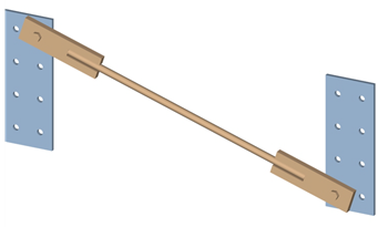
 Used to create a rod and plates
to connect existing plates.
Used to create a rod and plates
to connect existing plates.


 OK
OK
 Cancel
 Help
Help
 Template
 Clone
Clone
 Info.
Info.