Modify Rebar tools

The general workflow is to use select the 2D Rebar reinforcement and then apply one of the options to modify the Main Bar Attributes, adjust Bar End Details, edit Bar Range Display and/or use Main Bar Labels, followed by clicking the option to Save Modified Bar to write changes to the database (dgn).
Main Bar Attributes
 For any selected bar, you can
modify the appearance of the reinforcement bars by adjusting the parameters in
this dialog, and clicking on the Save Modified Bar option. When the program
draws the centerline of a reinforcing bar, the location of any centerline is
initially calculated in accordance with the default cover and bar diameter.
For any selected bar, you can
modify the appearance of the reinforcement bars by adjusting the parameters in
this dialog, and clicking on the Save Modified Bar option. When the program
draws the centerline of a reinforcing bar, the location of any centerline is
initially calculated in accordance with the default cover and bar diameter.

The parameters are explained below:
| Setting | Description |
|---|---|
| Full Size / Filled | The full size option ensures that the bars are drawn full size outline rather than being represented by centerline of rebar. The filled option causes the full size to be drawn as filled elements. |
| Color / Weight / Style | Although the program automatically maintains color,
line weight and line style of your reinforcement details, these attributes
relate to the centerline of bars only. The color, weight, and style are applied
independently of your normal DGN settings. You can select them in the
traditional manner.
All three of these parameters are ignored if your reinforcement resides on a Layer where Symbology is activated. In this situation, the color, weight and style for reinforcement on such a Layer is extracted from the Level Symbology table. |
| Ignore Level Symbology | When you check this option, the program ignore the Layer symbology settings (set within the Level Defaults dialog) and reverts back to this Main Bar Defaults dialog for the required color, weight, and style. |
| Use Construction Elements | When this option is OFF, all main bar elements adopt the Primary Class attribute. If the option is turned ON, they are created Construction Class attributes. Main bar elements of this type disappear from view when the option in Presentation is deactivated. |
| Hide | When checked, hides the bar elements. |
Bar End Details
 The Bar End Details dialog
contains many options for annotating bar ends:
The Bar End Details dialog
contains many options for annotating bar ends:

As the dialog appears, a small white circle is drawn at the first end of the bar to indicate the end being located. The Next End button moves the circle to the opposite end when work on the first end is complete. You can use it as many times as necessary, and at any time, to switch from one end to the other.
The control automatically switches to the second end of the bar after the first end is successfully located. The ENDX parameter in display.sys controls this behavior.
The second and third icons move the Tag closer or farther away from the bar end. Repeated selection of either of these icons initiates further movement.
The Bar End Details dialog always displays the state of the current bar end. As you switch from end to end, all options and edit fields update to reflect the conditions and location methods used on the selected end.
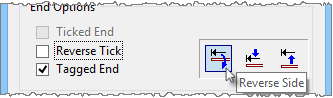
Ticked End and Tagged End
Ticked End and Tagged End options are used to highlight the ends of a bar. Often, when bars are congested or perhaps overlapping, a diagrammatic tick is placed at the end of the bar to clearly identify the bar end point. The Ticked End option is selected in these cases:
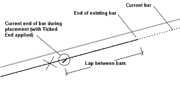
Notice, in this example of a lapped bar, the end of the current bar is not visible beneath the existing bar that it is lapped to. The end of the "Ticked End" identifies the actual end point.
The tick is always placed initially on the inside of the main bar away from the concrete face. If the opposite side is required, select Reverse Tick. The size, shape, color and weight of the tick are user-definable. Refer to the display.sys parameters TICK, TLEN, TOFF, TICF and TCOL for further information.
If the Ticked End option is selected, the Tagged End option becomes active. This additional feature is generally used when bars are scheduled. A small arrow is placed opposite the existing Tick and labeled with the current bar mark number:

Although the text appearing with the Tag is normally the Bar Mark number ("15" in the example), the content of the text is user-definable in display.sys using the parameter TAGT.
These parameters include TAGL, TAGA, TAGW, TAGH, TAGO, TAGI, ATAG, TAGT, and GCOL.
Bar Range Display
 The Modify Bar Limits tool opens
the Bar Range Display dialog.
The Modify Bar Limits tool opens
the Bar Range Display dialog.

Detail All Bars: Use this option to show all bars in range. Instead of showing just one of the bars in a range, you can detail all bars throughout the range when this option is checked.
Hide Delimiters: Hides the delimiters between individual bars, if the detail bars option is selected or between start and end of range if option for Detail All Bars is turned off. If delimiter lines for the current range are not required, select Hide Delimiters. Care should be taken when turning delimiters off. Existing bar labels may have been extended from these delimiters.
Dual: Use this option to show all dual bars in range. You can detail all dual bars throughout the range when this option is checked.
Radial: Use this option to show all radial bars in range. You can detail all radial bars throughout the range when this option is checked.
Offset: You can use the offset buttons to increase or decrease the spacing between the initial bar location and reference concrete face.
Delimiter Type and Adjustment
Several delimiter styles are available within the Delimiter Type icon tool box. The delimiter style can be selected (and re-selected) at any stage of the detailing process. Each of these delimiter types is applied in the same manner to radial bar ranges as you would do to parallel bar ranges.

The delimiters could be internal or external, and can be adjusted (increased or decreased incrementally).
The first icon represents the default delimiter style where a delimiter line is extended out from both sides of the typical bar to each external limit of the range.
The next two icons cause the first or last bar in the range to be drawn (respectively). A single delimiter line is then extended from this external bar to the opposite side of the range.
The forth icon details both the first and last bars. A delimiter line is drawn across the range to link both bars.
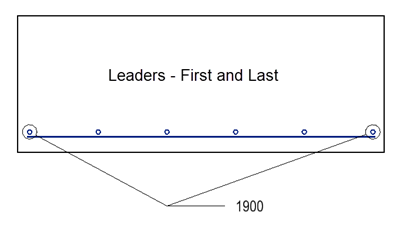
The last two Delimiter Type options allow you to move the delimiters beyond the ends of the bars in the range. The delimiter lines can also be placed outside the concrete outline if required. The first of the external delimiter types extends a leader line from the 'typical' bar in the range. Two leaders are also added at the start and finish limits.
The external delimiter lines are placed at an initial minimum distance from the end of the bar range. The distance is configured using the DLMO display.sys parameter.
If your preference is for the delimiter lines to be placed outside the concrete arrangement, select Face pushbutton in the External Delimiters box, then select the concrete face from which the delimiters are to extend. The current delimiter offset is transferred immediately from the end of the bar range to the concrete face. The delimiter lines are repositioned outside the selected face and the leader line from the typical bar is extended to meet them.
The distance between the end of the typical bar and the start of the leader line is determined by the display.sys parameter DLMG.
You can cut the extended leader line at its intersection with the selected concrete face. Select the Break Leader(s) at Face option and gap is inserted at the face. The size of the gap is controlled by the display.sys parameter DLMC.
You can apply these same techniques to the second external delimiter type (the last icon in the Delimiter Type tool box) – the one where delimiter lines are extended from the first and last bars in the range.
Often the location of the delimiter line conflicts with other details, or labels, or perhaps some part of the concrete outline. In these situations, the delimiter location requires adjustment. Using normal Platform commands, such editing is normally very time-consuming. however the program can perform the adjustments in an instant.
Simply select the left or right arrow icons (to the right of the Delimiter Type tool box). The delimiter lines, along with any labels that may be attached, are automatically adjusted up and down the range until the appropriate location is finalized.
Bar Display: Use these options to display Full Sized bars, filled elements, or if you wish to hide bars from display.
Main Bar Label
 The main bar label dialog is used
to define labels using the types and label text settings.
The main bar label dialog is used
to define labels using the types and label text settings.
Label Type: 1. Arrow Label
The Main and Longitudinal bars can be labeled with the Arrow Label option. The bar range detailing process offers three different labeling methods. The Arrow Label used for Section detailing is still available for bar ranges, but two extra methods - Line Label and Delimiter Label - are included to cater for the particular nature of bar range details. As the Labels dialog appears, a prompt is displayed asking you to indicate of the start point of the label. When a data point is selected, the program uses its auto-snapping facility to automatically attach the label line to the nearest point on the main bar. "Main Bar Labels" are only ever attached to main bar reinforcement. Longitudinal bars or other reinforcement elements are therefore automatically ignored during the auto-snapping process. Remember, as with any of the 2D Rebar labeling options, snaps are never required. It is always much quicker to indicate an approximate point, then let the software determine the accurate location. With a location for the start point confirmed, the first label line appears dynamically beneath the cursor. Select a data point to confirm the end of the first line, then continue selecting data points until all label lines are located (up to an allowable maximum of four). Select the Reset button when all lines are located. The label text then appears, extended from the last label line. Up to four lines of text are attached to any one Arrow Label simply by entering it into the Label Text edit fields. Alternatively, you can select a predefined label from the Presets list.

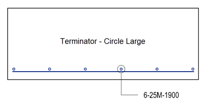
Instead of an "Arrow" on the end of the first label line, a variety of other Terminators could be selected. Options include None, Arrow, Circle (Small), Circle (Large), Dot and Stroke.
Also, a different Position might be required. These options control the position of the lines of text relative to the end of the label line. Options include Adjacent, Between, Above, Below and Centered.

In situations where the first label line (extending from the bar) must be placed obliquely, activate the Oblique 1st Line toggle. During placement, the remaining leader lines are locked at an angle of either zero or 90³, if Angle Lock is On, or can move through random angles if Angle Lock is Off.

The Construction Lines option sets Construction Class to all label lines (but not the label text). The View Settings control whether these label lines are seen or not – refer to the Constructions attribute.
As an item in the Presets menu is selected, the text fields below are filled with the chosen labels.
The items found in the pop-up list are simply representative of the label actually produced. The text each Preset Text item loads into the edit fields usually includes Preset Text codes. It is only when the codes are displayed on the drawing that they appear as appropriate reinforcing variables (e.g. bar diameter, spacing, bar mark number etc.). Suppose "5-Y20-300" has been chosen. This Preset Text field automatically loads the text "$n-$d-$ns". The keywords $n, $d and $ns relate to the number of bars in the bar group, and the bar group diameter and the nominal bar spacing (respectively).
You can use the four icons to the right of the Text Location tool box to make final adjustment of the text once its general location is established. The presets.sys parameter DIMA controls the amount by which the text is moved each time either of these icons is selected.
When placement of the Arrow Label is complete, you can halt the labeling process by either closing the dialog, or by selecting another icon from the main bar placement tool box.
A maximum of 10 main bar labels is allowed on any one bar. To create additional labels, select the New button. The labeling procedure then immediately restarts. An indicator circle is placed at the end of the first label line to indicate the current label. Selecting Next causes placement to move to the next available label. The Delete button deletes the currently selected label.
Arrow Label for Bar Range
The Arrow Label is constructed in the manner described above for Section bars. The same options are all available.
When the first point of the Arrow Label is indicated, the program auto-snaps the point to either the main bar or the delimiter lines, as shown in the examples below:
Consider the situation where more than one range has been included in a bar range detail. Each range could be labeled individually with an Arrow Label. Alternatively, one label could be added, then automatically repeated across all other ranges using the Repeat All Ranges option. The following example shows its use:

In the example, the original label is attached to the range on the left, the duplicate on the right. Note the preset text used in this example is "$n-$d-$ns" (i.e. number of bars - diameter - nominal spacing). The range on the right was placed with a nominal spacing of 100. The label text is formatted automatically to account for the modified number of bars etc..
Repeat All Ranges operates only when Arrow Labels are attached to delimiter lines. A label attached to a main bar cannot be repeated for obvious reasons.
Repeated labels are always regarded as part of the single original label. Duplicate labels that are automatically generated cannot be modified individually. If minor variations are required for any of these labels, individual labels must be used. If additional ranges are attached to an existing range after a 'repeated' Arrow Label is already placed, the new range is automatically labeled with the same repeated Arrow Label. The new label appears as soon as the start and finish limits of the range are located.
The Lock To Origin toggle button becomes available for selection when you begin placement of an Arrow Label to bar ranges.

When you activate this option, the first leader line snaps automatically to the circle at the intersection of the main bar and delimiter line. This applies to all delimiter types including the ‘external’ ones.
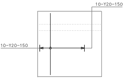
Label Type: 2. Line Label
The Line Label is selected from the middle icon in the Type icon tool box. When selected, the label text is moved dynamically up and down the main bar and delimiter lines as the cursor is moved. The text location is auto-snapped to the nearest point on the bar range until a data point is selected to finalize the text location.
The following example shows the two basic placement locations - either along the main bar or along the delimiter.

When additional ranges are added, the text auto-snaps to the new ranges as it does to the primary range. Use of the Repeat All Ranges option duplicates the current Line Label through all ranges. Again, as with Arrow Labels, Line Labels are only repeated when attached to a delimiter line.
Repeated labels are always regarded as part of the original label. Duplicate labels that are automatically generated cannot be modified individually. If minor variations are required for any of these labels, individual labels must be used.
If additional ranges are attached to an existing range after a 'repeated' Line Label is already placed, the new range is automatically labeled with the same repeated Line Label. The new label appears as soon as the start and finish limits of the range are located. Preset text variables used in your text are evaluated dynamically as the line label moves from one range to the next.
Label Type: 3. Delimiter Label
Delimiter Label is the second of the label types applicable only to bar range details. It is selected from the third icon in the Type icon tool box.
This label type extends a straight line from the end of a selected delimiter line. As soon as the option is activated, you are prompted to "Indicate end of delimiter for start of label". A data point should be indicated in close proximity to the delimiter from which the label is to be extended. Bentley Rebar auto-snaps to the closest delimiter end and begins dynamically to adjust the end of the first label line. The system then awaits indication of a second data point defining the end of the first label line. Note the first label line is always extended outwards from the chosen delimiter, even thought the data point may be indicated between the delimiter ends. Two examples of the Delimiter Label are shown below:
Text for the label is entered in the normal manner. The Presets pull down menu displays a user-defined list of preset text options as shown below.
As an item in the Presets menu is selected, the text fields below are filled with the chosen labels. Let's assume "5-Y20-300" has been chosen. This Preset Text field automatically loads the text "$n-$d-$ns". The keywords $n, $d and $ns relate to the number of bars in the bar group, and the bar group diameter and the nominal bar spacing (respectively).

Longitudinal Bar Label
 Used to label longitudinal bar
labels, group label, and bar mark labels.
Used to label longitudinal bar
labels, group label, and bar mark labels.

- None - Label text is denoted by leader lines only without any terminator symbol.
- Arrow - Label text is denoted by leader lines with Arrow at end.
- Circle (Small) - Label text is denoted by leader lines with Small circle at end.
- Circle (Large) - Label text is denoted by leader lines with Large circle at end.
- Dot - Label text is denoted by leader lines with Dot at end.
- Stroke - Label text is denoted by leader lines with Stroke at end.


- One Leader - Selected long bar is denoted by one leader.
- First and Last - First and last long bars from selected group are denoted by leaders.
- Between - First and last long bar along with middle bar from selected group is denoted by leaders.
- Specify - Long bars are denoted with leaders as per specified number.
- All - All long bars from selected group are denoted by leaders.
- Dual - First two and last two long bars from selected group are denoted by leaders.


Strike-Thru – When checked, draws strike through pattern to longitudinal bar.
Oblique 1st line – When checked, places the first label line that is extending from the bar obliquely.
Angle Lock (0,90) – When checked, the remainder leader lines are locked at an angle of either 0° or 90°.
Curved – When checked, enables placing curved leader lines.
Label Types: Arrow, Dimension Style, Bar mark.For Dimension Style label, there are two main groups of modifying dimensions, as you can see are Dimension Geometry and Dimension Text. Within Dimension Geometry there are five Adjustment and Text Location icons and four pull down Terminator options which are supported in this tool box. The Dimension Text group box allows you to specify the text added to the dimension.

The Presets pull down menu displays a user-defined list of preset text options.
As an item in the Presets menu is selected, the text field below is filled with the chosen label.
Adjustment Tools: The first icon in the Adjustment tool box switches the side on which the dimension appears. The second and third icons move the label closer or farther away. For example, when pressing the third button, the label and associated dimension lines and delimiters move closer to the bar. The last two buttons in the tool box slant the label to the left or right.
The Text Location options consist of three icons from left to right that force the dimension text to the outside left, center, and outside right of the dimension lines respectively. These locations obey your preferences in the Dimension Settings dialogs. You can use the two icons to the right of the Text Location tool box to make final adjustment of the text once its general location is established. The display.sys parameter DIMA controls the amount by which the text is moved each time either of these icons is selected.
The Terminators menu displays the dimension line terminator options you normally find in your Dimension Settings dialogs. The terminator type is altered instantly whenever a selection is made.
When both dimension text and adjustments are finalized, the Modify Dimension box can be closed. Future selection of the Dim… button (in the Bar End Details box) restores the Modify Dimension box to its previous state
Field Bend
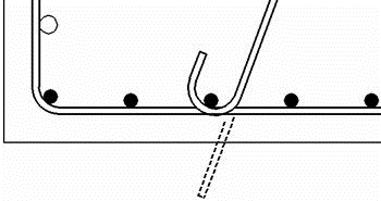
Problems associated with construction sequences or perhaps construction tolerances can sometimes necessitate bars being bent on site. Of course, this is only possible when the diameter of the bent bars are smaller. In the following example, the specification calls for one of the 180° bends on a single-legged bar to be bent on site.

This means the actual bar being scheduled (and produced by the bar manufacturer) is just a single-legged bar with one 180 degree bend. If it were manually detailed, you would make some adjustments to the length of the bar to account for the extended length of the unbent hook. With 2D Rebar, the process is completely automatic.
Simply place the bar with both hooks in place at the necessary final location. In the DV use the End Details icon and move to the end at which the on-site bend is to be made (in this case, it is the bottom end). Now select the Field Bend toggle button.
The bar detail is extended with a dashed line showing the development of the bar before bending on-site:
and in normal centerline mode (full-size OFF), the same detail appears as:

If you prefer to not show the extended dash line on the DGN file (a visual preference only), you can alter the value of the display.sys parameter FLDB. If you decide not to show the dashed line, it is your responsibility to label the end on which the field bend is placed.
Finally, in situations where one bar is lapped to another, the ends of both bars are often ticked to highlight both ends across the lap. If the current bar is lapped to another bar, and the end of the lapped leg is Ticked, the end of the other bar is automatically ticked by the program when the current bar is saved. If a Tag has been added to the Ticked End detail, the lapped bar is also tagged automatically as well.
Delimiter Alignment
A pull-down menu containing seven alignment methods is available within the Delimiter Alignment group box, as shown below

The Automatic method is the one used initially by the program each time a new bar range detail is created. You can decide to use a different alignment whenever you choose. One of these other alignment options is normally used when a bar range is skewed or the concrete faces at the ends of the range are not orthogonal to the bars in the range.