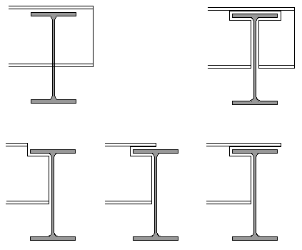
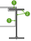
Cope
Used to cope steel elements.
Accessed from: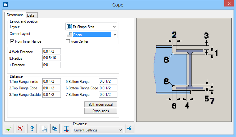
Dialog Controls
| Setting | Description |
|---|---|
 OK OK
|
Closes the dialog and save your changes. |
 Cancel Cancel
|
Closes the dialog without saving changes. |
 Help Help
|
Opens online help. |
 Template Template
|
Saves and retrieve (Using Templates) settings to be used on other projects. |
 Clone Clone
|
Transfers the data of the current cope directly to several copes (must be created as new copes). |
| Favorites | |

|
Allows an unknown shape to be clicked. The flange thickness is then entered in the input fields for 1. Top Flange Inside and 5. Bottom Flange. If you have entered a value in the +Distance field, this value is added. |
  Show /Hide
Preview Show /Hide
Preview
|
Opens or closes, respectively, a flyout panel to display an illustration based on the tool. |