User Dimension Points
 Used to specify user defined
dimension points to
OpenBridge Modeler objects, for drawing
generation.
Used to specify user defined
dimension points to
OpenBridge Modeler objects, for drawing
generation.
Some steel constructions are very complex so that the system is not always able to determine the suitable dimensioning automatically. Often it is even not possible to find all suitable points because important reference dimensions such as, weld check dimensions, or similar values have to be defined individually and are not automatically known to the system.
For this purpose, you can define dimensioning points directly in the model for the derivation of group drawings or overviews; the system has to be forced to dimension them. In contrast to the subsequent manual dimensioning of 2D workshop drawings, the advantage of this function is that they can be updated at an automatic 2D-update.
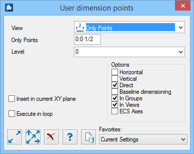
| Setting | Description |
|---|---|
| View | Specifies how the dimensioning points have to be
depicted in the 3D-model.
|
| Only Points | Sets the size to be used for depiction of the two measured points. |
| Level | Sets on which layer the object has to be inserted. |
| In Current XY Plane | The picked points are projected onto the current view plane. Thus, an object snap into the depth is avoided. |
| Execute in Loop | The command is carried out as a loop. You can insert several manual-dimensioning objects one after the other without having to call the function again each time. |
| Options | Check to apply one or more of the following
dimensioning options:
|
 Single Single
|
Click on this button to add a single dimensioning object consisting of the start and target point. You first have to click on the group this dimensioning object is to be assigned to. Then, you click on the start and afterwards on the target point of dimensioning. |
| Multiple
|
Click on this button to add a single dimensioning object consisting of the start and target point. You first have to click on the group this dimensioning object is to be assigned to. Then, you click on the start and afterwards on the target point of dimensioning. |
 Cancel Cancel
|
Closes the dialog without saving changes. |
 Help Help
|
Opens online help. |
 Template Template
|
Saves and retrieve (Using Templates) settings to be used on other projects. |
| Favorites |
Example
The following is an example of the variants in case of multiple dimensioning points: The dimensioning points which first seem to be similar in the 3D-model (above) create different results in the 2D-drawing (below). For both objects, only the ‘Horizontal’ dimensioning direction has been activated.
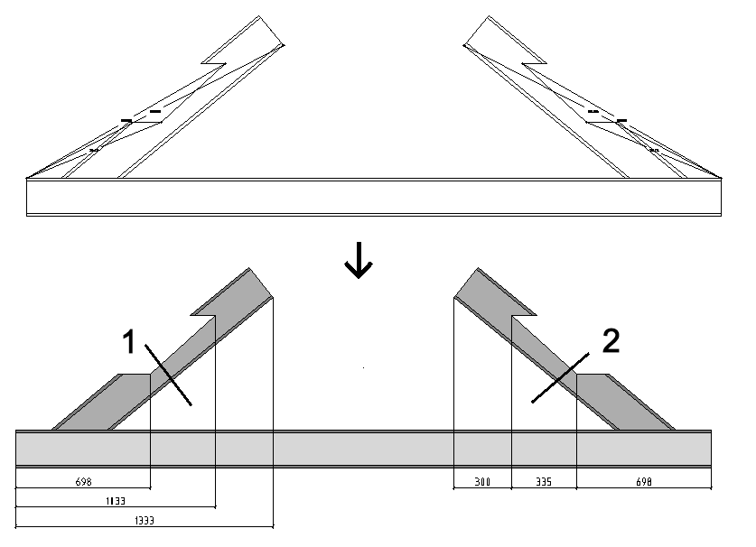
The dimensioning object on the left here has been created with the option 'Baseline Dimensioning’ so that all dimensioning points refer to the left reference point (1). On contrast, the right dimensioning object has been created without this option, and a continuous dimensioning chain (2) is created with the right reference point.
Selection of Views
In principle, dimensioning objects have to be assigned to a group or to an assembly, even if the dimensions only appear in an overview drawing. At use in nested group structures, they are always assigned to the lowest hierarchy and controlled by means of their parameters at detailing.
If you pick e. g. the subordinate part of a subgroup which is part of a standard component part group, the dimensions will only be displayed in the detailing of the component part group, when manual dimensioning points have been activated there for subgroups.
At the later detailing, the dimensions are only displayed in the view that corresponds to a view at insertion (or to the opposite direction). Therefore, you should insert a dimensioning object on a component part in the view in which later you want to see the length to be dimensioned.
Hint: When the dimension doesn’t appear in the desired view, it was probably inserted in a wrong UCS plane and perhaps the dimensioning points were only corrected later. You can check this by making display the coordinate system of the dimensioning object. Its X/Y-pane has to be parallel towards the view plane.
If you want to see the length in two views that are not opposite to each other, from view direction, you have to add the dimensioning object for a second time.
Modification of Dimension Points
You can modify an existing dimensioning object later via the Structural Properties by e.g. adding further dimension points using the PLUS button or by removing them using the MINUS button.
Other properties such as the desired dimensioning directions can also be modified.
All picked dimension points can be moved later by means of the handles, if you modify your construction.
 Shape Default
 Shape Pick
 Endplate Default
 Endplate Pick