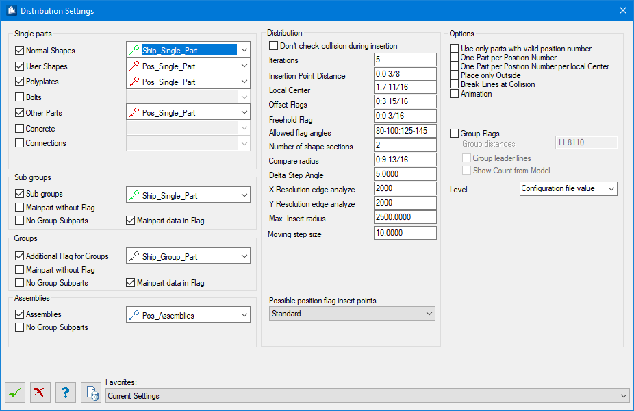
Distribution Settings dialog
 Used to specify the
pre-settings for the automatic distribution of position flags. You can define
the position flag styles and different optimizations.
Used to specify the
pre-settings for the automatic distribution of position flags. You can define
the position flag styles and different optimizations.
| Setting | Description |
|---|---|
| Single Part, Sub groups, Groups, Assemblies —Selection list | Here, you specify to which parts position flags
have to be attached. After having selected a part type, you can choose a
position flag style for this part type which has to be used to display the
flag.
No group sub parts means that group sub parts are not given a position flag. This is equally valid for subgroups and assemblies. |
| Distribution | Sets the dimension details and offsets in distribution considering the collisions: |
| Don’t check collision during insertion | At distribution the position flags are placed on the component part without verifying the surroundings of the part. This is the fastest distribution method, however the most inexact method as well. |
| Iterations | This value indicates how often a new position has to be searched for a position flag. The higher the value, the better the positioning result will be, but the longer the search for a suitable position of the position flag. |
| Insertion Point Distance | The minimum distance between the insertion point and the end of the position flag’s guideline |
| Local Center | Your model is divided into different positioning sections with so-called local centers. The position flags are arranged in a circle around these centers and inserted. This value sets the minimum distance between two local centers. |
| Offset Flags | This value indicates the projection of the flag beyond the edge of the visible geometry. |
| Freehold Flag | This value specifies the minimum distance between two neighboring position flags. |
| Allowed Flag Angle | In this field, you specify how the position flags have to look like. The angle is measured between the guideline and the alignment of the text of the position flag. The angle is always indicated as angle area, because an exact angle specification cannot be carried out with distribution algorithm. |
| Number of Shape Sections | For long shapes you can specify on how many positions except the center of the shape position flags have to be placed. At the value 0, the position flags are placed on the center. |
| Compare Radius | Here you specify the radius to be used for verifying the current position flag with regard to collisions with existing part geometry, position flags, elevations, texts or dimension texts. The bigger the value, the longer is the processing time. |
| Options | Sets the various positioning options:
|
| Group Flags | Position flags referring to parts with identical
position or shipping number are arranged to form a common flag.
The insertion points mustn’t exceed the maximum distance to form a group.
|
| Level | Sets the level selected from available drop-down options. |
 OK OK
|
Closes the dialog and save your changes. |
 Cancel Cancel
|
Closes the dialog without saving changes. |
 Help Help
|
Opens online help. |
 Template Template
|
Saves and retrieve (Using Templates) settings to be used on other projects. |
| Favorites |