OpenBridge Modeler

Assign Parts dialog

Depending on the type, certain component parts can be assigned to any standard dimensioning group or to the special component part groups. Select the desired group and then right-click > Add Component Partsmenu. The following dialog opens:

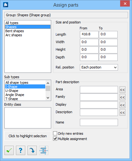
The content of the selection lists depends on the type of dimensioning group, on the settings and on the component parts already assigned to.

SettingDescription
Selection Lists Part type selection is made here.
Upper List Here you select the principle component part type (main type) such as shapes, plates, etc. you want to add.  If you do not want any particular restriction here, select the ‘All types’ entry.
Subtypes Here you select a subtype with which you can limit the selection of the upper list. However, subtypes are not available for all component part types.  Thus you can limit an assignment e.g. only to all U-shapes. Select the entry ‘All Shape Types’ if you don’t want to limit the assignment. 
Entity Class A list of entity class is displayed here. Select the applicable class from here.
Size and position Settings for defining part size and object position relative to view plane.
Length, Width,... Enter an area with which you limit the selection in the fields From and To. If you enter the value 0 in both fields, this size will not be taken into consideration.
Relative position Used to select the position of the part with regard to the projection plane used to narrow the selection. If ‘From front only’ is selected, the parts under that level (local negative z-direction) will not be taken into consideration. 
Part Description Settings for describing part classes.
Note: Please note that, for the input fields for the various classes or part descriptions, leaving the field empty is the same as ‘Any’, i.e. the value will not be taken into consideration. If on the other hand it is necessary to filter out parts that have not been allocated to any family, the value ‘None’ may be entered.
Area Enter the area class of the part (or a section of the area class with placeholders) used to limit the selection.
Family Enter the part family (or a section of the part family with placeholders) used to limit the selection.
Display Enter the visibility class (or a section of the visibility class with placeholders) used to limit the selection.
Description Enter the description of the part (or a section of the part description with placeholders) used to limit the selection. In 3D models every part can be given a description, which can then be used to compile a separate classification. These descriptions are not available for integrated elements, but both can be used in combination.
<< (Select from List) If this button is clicked, any valid entry may be selected from a list of the currently available area classes, visibility classes, part families or part descriptions.
Name Enter the name (or a wildcard substring of a section of the name with placeholders) to be used to limit the selection.
Only New Entries If this field has been checked, already added component parts are not displayed any more, even if they are situated in other dimensioning groups. Comparison is only made via main type so that the complete type is hidden even if there had been a limitation before. Thus, you can see which types have not yet been seized by dimensioning. In this case, multiple assignments are not possible (any more).
Multiple Assignments If this field has been checked, component parts or areas of component parts can be added several times unless it is a matter of the same dimensioning group. For more detailed information about multiple assignments and wildcards, See "Automatic Assignment Check".
Click on this button to add your defaults as new assignment or to modify the selected assignment accordingly.
Click this button to select part, including its size range, will be added to the dimension group.

Example

The neighboring example shows the dimensioning of a construction having approximately identical shape types and shape lengths.

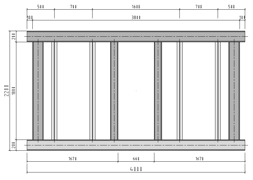
With the help of component part description, you can nevertheless automatically generate a dimensioning which shows the connection of the component parts with each other in a reasonable way.

Modify and Delete Assignment

First select the desired assignment in the tree structure and then call the context menu.

Modify the assignment using the entry Modify Part. Then, the above-described dialog for assignments opens where the current setting is displayed. Now, you can modify the data and make new assignments.

Delete the assignment using the entry Delete Parts. It may be that the component part or the part area will be processed by other groups.

Automatic Assignment Check

When component parts are assigned, the program automatically checks whether the type, name or size areas overlap and therefore the result would be an indefinite assignment. If this is the case, the new assignment will not be accepted and an error message will be displayed.

The check is made at each insertion or modification of assignments and depends on the option Multiple Assignments. If this option has been activated, the check is only made in the current dimensioning group – the assignment can be repeated in another group of the part area. If multiple assignments option has been deactivated, the program checks the complete part area by means of all groups that a component part will be registered only once.

The following table shows some examples of desired assignments:
Existing Assignment Additional New Assignment Description
Shapes Shapes not possible
Shapes Shapes, only U-Shapes not possible
Shapes, only L-Shapes Shapes, only U-Shapes OK
Shapes, up to 2000 mm length Shapes, from 1500 to 2500 mm length not possible
Shapes, up to 2000 mm length Shapes, from 100 mm height onward not possible
Shapes, up to 2000 mm length Endplates, from 100 mm height onward OK
Shapes, Name=HEA* Shapes, Name=HEB* OK
Shapes, Name=HE* Shapes, Name=HEB* not possible

A question mark, ?, can be used as wildcard for any single character in the name or in the component part description.  An asterisk, *, can be used for any sequence of characters. 

It is true that you can use the symbols as you like, but a correct check with regard to overlapping only takes place for the symbol * at the beginning and/or end.