Profile Curve Between Elements
 Used to construct a vertical curve between two designated elements.
You can access this tool from the following:

Use the Profile Curve between Elements tool to construct a vertical curve between two designated elements.
-
Select the Profile Curve between Elements icon.
Note: If your View isn't in Profile mode, a message will indicate that you need to Open Profile Model. -
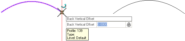
When you move the cursor into the Profile View, it is equipped with a command prompt requesting that you "Locate First Profile Element", so move the cursor to the element from which you wish to draw a curve then data point (left-click) on it.
-
Use one of the following methods to set the Back Vertical Offset:
-
When prompted to Locate Second Profile Element, move the cursor to the element to which the curve must extend then data point.
-
When prompted to Locate Second Profile Element, move the cursor to the element to which the curve must extend then data point.
-
Use one of the following methods to set the Ahead Vertical Offset:
-
Use one of the following methods to designate a point through which the curve must pass (navigate the options by striking the left or right arrow keys):
-
To trim the element at the intersection of the curves or to extend the new curve to intersect with the old, your Offset value must be zero. Strike the down arrow key to choose the Back option then strike the Enter key.


Vertical Curve Type
The option for curve type can be changed in the dialog or by pressing Shift key on keyboard. Supported curve types are:
- Parabola - Symmetric Parabolic Curve
- Asymmetric - Asymmetric Parabolic Curve
- Circular - A simple curve defined by radius
Properties
To View the new element's properties, equip the Element Selection tool.

Select the element in the View then let the cursor hover over the selected element. Click the Properties icon to access rule data for the chosen element.
Custom Tool
These pre-customized versions provide a simplified prompt sequence for many common construction tools. Right-click on the Profile Curve between Elements icon then choose Show/Hide Arc from Element Tools to access the following option:
-
Parabola between Elements - Creates a parabola between two elements, Offsets are locked at zero
-
Asymmetric Parabola - Creates an asymmetric parabola between two elements, Offsets are locked at zero
-
Circular Curve between Elements - Creates a simple profile radius between two elements, Offsets are locked at zero