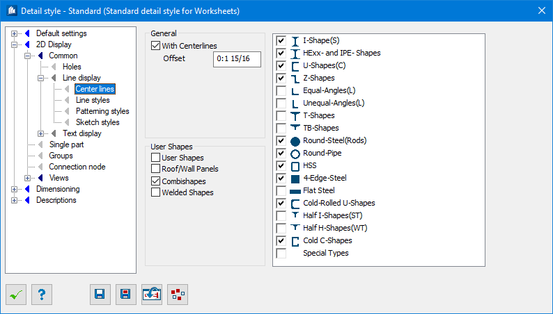
Detail Style-2D Display - Common - Line Display-Center Lines tab
| Setting | Description |
|---|---|
| With Centerlines | The center lines of the component parts selected on this dialog tab are displayed. |
| Offset | Here, you specify the excess length of the center line beyond the two ends of the shapes. |
| User Shapes | Center lines for user shapes are depicted. |
| Roof/Wall Panels | Center lines for roof-wall shapes are depicted. |
| Combishapes | Center lines for combishapes are depicted. |
| Welded Shapes | Center lines for welded shapes are depicted. |
| Shape List | Select for which types of different standard shapes the center lines have to be depicted by highlighting them in the list. |
When displaying overview plans, you can use freely definable object groups in combination with standard settings to control how center lines are displayed. For further information please see the definition of 2D display in overviews in this manual.