Arc Between Points
 Used to create an arc between points.
You can access this tool from the following:

Arc Between Points creates an arc between points. The most common usage is Arc between 3 points, but other variations are available.
Points can be defined in several ways:
-
A click in the graphics
-
Defined using Civil AccuDraw
-
Snapped relative to other elements
-
An existing geometry point element
Arc Between Points Dialog
Any of the inputs may be locked in the dialog when the tool starts or at any time while the tool is active. All of the values on the dialog are dynamically updated as the cursor moves.
Six Workflows for Creating the Arc
-
Start Point, Radius, and Sweep Angle (or length)
-
Center Point, Radius, and Sweep Angle (or length)
-
Start Point, End Point, and Pass-Thru Point
-
Start Point, Pass-Thru Point, and End Point
-
Start Direction, End Point
-
Start Point, End Direction
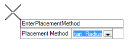
Workflow 1 (Start, Radius Method)
| Prompt Number | Prompt For | Options |
|
1 |
Placement Method |
Start, Radius |
|
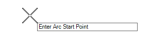
2 |
Start Point |
Arc Start Point |
|
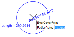
3 |
Center Point |
Radius |
|
4 |
Sweep Angle/Length |
Sweep Angle or Length |
-
Select the placement method.
-
Select the start point of the arc.
-
Select the center point at which radius can be locked.
-
Select the end point at which sweep angle or length can be locked.
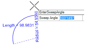
Use left/right arrows to toggle between sweep angle and length.
The sweep angle or the length can be locked.
Workflow 2 (Center, Radius Method)
| Prompt Number | Prompt For | Options |
|
1 |
Placement Method |
Center, Radius |
|
2 |
Center Point |
Radius |
|
3 |
Start Point |
Radius or Start Direction |
|
4 |
Sweep Angle/Length |
Sweep Angle or Length |
-
Select the placement method.
-
Select the center point of the arc.
-
Select the center point at which radius can be locked.
-
Select the end point at which sweep angle or length can be locked.
Workflow 3 (Start, End, Pass-Thru Method)
| Prompt Number | Prompt For | Options |
|
1 |
Placement Method |
Start, End, Pass-Thru |
|
2 |
Start Point |
Arc Start Point |
|
3 |
End Point |
Radius, Length, or Sweep Angle |
|
4 |
Through Point |
Radius, Length, or Sweep Angle |
-
Select the placement method.
-
Select the start point of the arc.
-
Select the end point at which the radius can be locked.
-
Select the pass-thru point in which radius, sweep angle, or length can be locked.
Workflow 4 (Start, Pass-Thru, End Method)
| Prompt Number | Prompt For | Options |
|
1 |
Placement Method |
Start, End, Pass-Thru |
|
2 |
Start Point |
Arc Start Point |
|
3 |
Through Point |
Radius, Length, or Sweep Angle |
|
4 |
End Point |
Radius, Length, or Sweep Angle |
-
Select the placement method.
-
Select the start point of the arc.
-
Select the pass-thru point in which radius, sweep angle, or length can be locked.
-
Select the end point, allowing radius to be locked.
Workflows 5 & 6 (Start Direction, End & Start, End Direction Method)
Start Direction, End
| Prompt Number | Prompt For | Options |
|
1 |
Placement Method |
Start Direction, End |
|
2 |
Start Point |
Start Tangent Direction |
|
3 |
End Point |
Start Tangent Direction |
|
4 |
Start Tangent |
Start Tangent Direction |
Start, End Direction
| Prompt Number | Prompt For | Options |
|
1 |
Placement Method |
Start, End Direction |
|
2 |
Start Point |
End Tangent Direction |
|
3 |
End Point |
End Tangent Direction |
|
4 |
End Tangent |
End Tangent Direction |
-
Select the placement method.
-
Select the start point of the arc in which the start tangent direction can be locked.
-
Select the end point in which start tangent direction remains on the prompt and can be locked.
-
Select the start tangent direction or end tangent direction.
Manipulators
Use Element Selection to select the arc and see its edit manipulators.
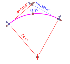
When the arc is placed without snaps and without Civil Accudraw constraints you will see the manipulators as shown above. The manipulators can be used to edit the line as follows:
-
The radius and length text manipulators can be clicked to allow editing of the value
-
The arrows parallel to the arc can be clicked to extend or trim the arc
-
The end point arrows perpendicular to the line can be clicked to move the end points perpendicular to the arc
-
The dot shaped manipulators at the end points can be clicked to move the end point
-
The dot at arc mid-point can be clicked to dynamically move the radius
-
The dot at the pass-thru point can be clicked to move the pass-thru point
-
The dot at PI can be clicked to move the PI point
-
The arrows at PI can be clicked to slide the PI point along the back or ahead tangent
Properties
Rule data is also accessible in the properties of the arc. Select the arc and click Element > Information. Most data in the property pane can be edited to change the arc definition.
Note: When you review geometry the Element Information dialog displays the terrain models that the geometry belongs to, if any.