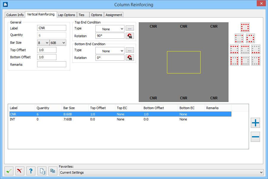
Column Reinforcing - Vertical Reinforcing tab
As many different types of bars as necessary can be entered, with each type of bar saved as a line in the detail table. As each type of bar is entered, indicate the location(s) of that type of bar by clicking on the bars in the cross section.
| Setting | Description |
|---|---|
| General group |
|
| Bottom / Top End Conditions | The following descriptions apply to both top and
bottom options.
Type – Select the type of end condition for each position:
|
| Rotation | Type a rotation angle (in degrees). Click
 to rotate the bar by increments
of 90 degrees. to rotate the bar by increments
of 90 degrees.
|
 Edit End Condition
Values Edit End Condition
Values
|
When you select an end condition type, the standard
values and angle are applied. If necessary, click
Edit End Condition Values
 to enter custom end
condition settings. See
Rebar End Properties dialog. to enter custom end
condition settings. See
Rebar End Properties dialog.
|
| Status | Indicates if you have used standard or user-defined end conditions. |
| (Preview) - the cross section diagram | The diagram displays the current number of bars as specified from the Column Info tab. The bar arrangement buttons on the right side of the cross section diagram are used to assign each bar Label to various bar patterns in the cross section. |
 Rectangular Patterns Rectangular Patterns
|
Vertical Reinforcement Patterns for Rectangular columns. Displays 9 patterns, each when clicked highlights the cross section illustration in the preview. |
 Circular Patterns Circular Patterns
|
Vertical Reinforcement Patterns for Circular columns. Displays 3 patterns, each when clicked highlights the cross section illustration in the preview. |

|
Adds a new line to the detail table and clears the
controls in the editing area allowing a new bar to be entered.
The table displays the details for each vertical bar type added to the reinforcing cage. |

|
Deletes the current line from the corresponding table. |


