Edit Superelevation Rule File
 Edits the XML-formatted
superelevation rule file.
Edits the XML-formatted
superelevation rule file.
You can access this tool from the following:

XML Superelevation
The superelevation calculator uses an XML-formatted rules file to calculate various aspects of superelevation. These files can calculate Max E rate for each curve of an alignment and the transition lengths needed to rotate the road bed from normal crown cross slope(s) to full superelevation cross slope (Max E). The sections that follow describe the schema of the XML file, and how it works.
How It Works
If a user selects a RateTable, then the Design Speed is populated by looking at what DesignSpeedRateTables exist in the rate table. If a user selects a RateEquation, then the Design Speed selection is populated with the Speed elements that are in the Speeds collection under the equation. Speeds don't have to be simple numerical values. For example, the Michigan standard has speeds of "60 Urban" and "Loop".
If the user is going to use Speed Tables for Transition calculations, then there must be a TransitionTable defined for each possible speed. TransitionEquations may or may not use speed as a variable.
Once the user has made their selections, and the code starts processing, if there are any UserVariables defined in the XML file, then a dialog box will pop up and allow the user to make changes to any/all of these values.
The code will then start processing for each curve. Once the Max E Rate and the Transition Length have been processed for a curve, the code checks to see if the XML file has any CustomKeyStations. If so, it will process these. CustomKeyStations allow for the addition of additions superelevation stations (see MTO 1% cross slope requirement), or the adjustment of the standard superelevation key stations (see AR DOT or SC DOT). Note: equations for custom key stations are written for curve entry (NC - FS). Curve exit transition calculations are automatically mirrored.
Once any key stations have been adjusted, the code will look for TransitionOverlapOptions and see if any additional adjustments should be made to the calculated stations.
Writing Equations
When writing equations, there are 3 types of variables available. Global variables are variables defined by the system, or calculated during processing. Local variables are defined in the XML file at various locations and can be identified as the "Variable" elements. These variables are used in the equations in the xml file and cannot be changed by a user at run time. User variables are also defined in the XML file. These are variables the can be set/changed by the user at runtime without having to modify the XML file. They are defined in the "UserVariables" collection in the XML file.
This is a list of the global variables:
- Global Variables for MaxE calculations:
- Global Variables available
for Transition calculations - include all above plus: (Note that the standard
stations have already been calculated, but can be changed here)
- TransitionLength - calculated transition length value
- HasSpiral - "true" if spiral exists, otherwise false
- StartOfSpiral - station of spiral start
- SpiralLength - length of spiral
- StartOfArc - station of arc(curve)start
- NCRadius - radius at which E rate caluclation is normal drown slope (maximum radius)
- RunoutStation - calculated start of transition
- RunoffStation - calculated zero cross slope location
- ReverseCrownStation - calculated reverse crown station
- FullSuperStation - calculated location of full super
- Global Variables
available for transition interference (overlap) - not yet defined in the XML or
coded:
- OutLength - transition length exiting first curve
- OutFullSuper - first curve full super station
- OutRunoffStation - first curve zero cross slope location
- OutRunoutStation - first curve normal crown location
- InLength - transition length entering second curve
- InRunoutStation -second curve normal crown location
- InRunoffStation - second curve zero cross slope location
- InFullSuperStation - second curve full super station
- The following math
functions can also be used in equations:
-
ABS, ACOS, ASIN, ATAN, CEILING, COS, COSH, FLOOR, LOOKUP, LOG, LOG10, MAX, MIN, MOD, ROUND, SIGN, SIN, SINH, SQRT, TAN, TANH, TRUNCATE
And these math values: FALSE, INFINITY, PI, TRUE
Math operators: +, -, /, *, ^ - power operator, %
Equations also support logical expressions in the form of:
"IF(logical expression)? execute if true : execute if false"
For example: equation="if(altDel == 0.0 and AltSuper == 0.0) ? Delta : altDel"
Logical expressions can also be nested, so another IF statement can be inside the true and/or false execution statement.
For logical expressions, the following conditional operators are available:
<, <=, =, ==, >=, >, <>. Take care when writing XML because "<" and ">" are special characters and must be written as "<" and ">" in raw xml. Some xml editors will do the conversion for you.
Logical Operators: IF, AND, OR, NOT
See the sample XML files for samples of how equations are utilized.
-
Main Elements of the XML File
This section describes top level elements of the superelevation XML schema for custom calculations
-
Units - required
Defines the units for the calculations and outpits.
Attributes:
- length – required - describes the units that the user is working in. Valid values are (meter, foot US survey foot
- stationRoundingValue – optional - If this value exists, all calculated station values will be rounded to this value. For instance, if the value is 0.2, then a station of 10+23.48 will be rounded to 10+23.4
- crossSlopeRoundingValue – optional - If this value exists, all cross slope values will be rounded to this value. For instance, a crossSlopeRounding value of 0.01 will round the cross slope of 2.3456% to 2.35%
-
DefaultSettings – optional
These settings are used to set the superelevation options(the inputs to the Apply Superelevation command) when creating superelevation from a corridor and an XML input file this is a - an automated process.
Attributes:
- eSelection – optional - Set this value to the name of the RateTable or RateEquation to use. Invalid values will result in using the first RateTable/RateEquation in the list.
- lSelection – optional - Set this value to "Speed Table" to use the transition tables. Otherwise, set it to the particular transition formula name. Invalid values will result in using the first (TranisitonTable/TransitionEqution) in the list.
- designSpeed – required - Enter a valid design speed (MPH/KPH).
- pivotMethod – required - Valid values here are: Crown, Inside Edge, Outside Edge, Left Edge, Right Edge, Divided Inside, or Centerline. If Divided Inside is used on an undivided roadway, if will be the same as using Crown. If an invalid value is entered, Crown will be the default. Centerline always uses the base alignment radius to calculate eRate. All other methods use the radius +/- the offset of the pivot to calculate eRate.
-
UserVariables - optional collection
These are variables that can be set by the user at runtime. The following types are supported. Strings, Integers, Decimal, and Boolean. Strings and integers can have combo box lists (SelectionValue elements). Integers and Decimals can have min and max ranges. If a variable name matches a TransitionOption or RunoutOption attribute name, then that option attribute will be exposed to the user.
The reason for these elements are to allow agencies to lock there XML files so they cannot be edited, but still allow the user limited access to change values, or control the calculations during the process of superelevation creation.
-
MaximumERateCalculations - required
Collection of RateTables and/or RateEquations used to calculate the maximum cross slope for a given curve radius. There must be at least one RateTable or RateEquation.
-
TransitionCalculations - required
Collection of TransitionTables and/or TransitionEquations used to calculation the runoff (ZeroCrossSlope to FullSuper) length. There must be at least one TranstionTable or TransitionEquation.
-
TransitionOptions - required
These settings are used to control how the values for ERate and transitions are calculated. They are, typically set by an agency standard, but can still be exposed to a user by a UserVariable if an agency wishes to allow the user to change one or more of these values.
Attributes:- interpolateTables – optional - If true, then all eRate and Transition tables will be interpolated. Otherwise eRate and Transition lengths will be the higher value. The default value is true.
- percentTransitionOnTangent – required – Percentage of transition that is not on the curve. Limit 0% - 100% (0.0 – 1.0)
- useSpiralLength – optional - If true, then wherever a spiral exists, it will be used as the transition length rather than the calculated transition. In this case, the percentTransitionOnTangent value will be ignored. The default value is true.
- lengthsAreTotalTransition – optional - If true, then table lengths are from normal crown to full super (runoff + runout lengths). If omitted then will default to false.
- transitionType
– optional - Type of transition in the diagram when there is a change in cross
slope rate. Allowable types are:
- Linear - no transition at vertices, all segments are straight
- Parabolic - creates a parabolic transition at each vertex. The length of the parabola is determined by the shorter of the value of nonLinearCurveLength and the shortest adjacent line segment.
- ReverseParabolic - fits a reverse parabola between the Normal Crown point and the Full Super point (the entire transition).
- Reverse Biquadratic - same as ReverseParabolic, but different equation
- Reverse Cubic - " "
- Reverse Parabolic Nonsymmetrical 1 - uses an ratio of ?? for start/end of transition parabolic lengths
- Reverse Parabolic Nonsymmetrical 2 - uses an ratio of ?? for start/end of transition parabolic lengths
- Reverse Parabolic
Symmetrical ??
If no transition type is specified, then the default is "Linear".
- nonLinearCurveLength – optional - maximum length of parabolic transition. This length will be reduced if the given length exceeds the length of the tangents on either side of the point. The default is 0.
- startInsideLaneRotationWithOutside – optional - If this flag is set to true, then the inside lanes will start rotating (early start) at the same location that the outer lane starts rotating, rather than starting at the point of reverse crown on the outer lane.
-
RunourOptions - optional
Normal runout is determined by matching the transition slope of the runoff section of the super transition. These values are a simple override to those calculations. If something more complex is needed then use CustomKeyStations.
Attributes:
-
CustomKeyStations - optional
CustomKeyStations are either overrides of the standard transition stations calculated for superelevation, or they are additional stations to be added to the lane(s). If the type of the key station is one of the standard types (NormalCrown, ZeroCrossSlope, ReverseCrown, or FullSuper), then it will replace the standard key station. If the type is Custom, then it will be added to the lane.
Attributes:
-
TransitionOverlaps - optional
These options are used to fix clashes when the exiting transition from one curve overlaps the beginning transition for the next curve. Contains a list of ReverseCurveAdjustmentOption and CurveCurveAdjustmentOption elements.
-
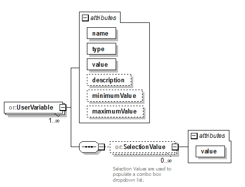
UserVariable - optional, unbounded
This is a variable that can be edited by a user at runtime. Boolean types are presented as a checkbox. Decimal types are presented as a string entry field (input will be validated). Strings and Integers will be presented as a string entry field, or if there is one or more selection values defined, then a combo box will be shown.
A UserVariable can be used to expose a TransitionOption or RunoutOption to the user for editing, and allow the equations access to that variable. To do this, simple set the name attribute of the UserVariable to the name of the option to be exposed. All other attributes of the UserVariable will be ignored. For instance, to expose the TransitionOptions->percentTransitionOnTangent, set the UserVariable name=percentTransitionOnTangent. The schema also requires that the type and value attributes also be set, but they will be ignored, and the user will be presented a field to enter a number between 0 and 1.
Samples of UserVariables can be found in the MI DOT and SC DOT sample xml files.
Attributes:- name - required - The variable name - cannot contain spaces or special characters.
- type – required - The type of variable (string, integer, decimal, or boolean).
- value – required – the default(starting) value for the variable.
- description – optional – shows up in the log file.
- minimumValue – optional – only used for decimal and integer types. Limits the user’s input.
- maximumValue – optional – only used for decimal and integer types. Limits the user’s input.
-
RateTable – optional, unbounded
Used to get a Max E Rate based on designSpeed and the radius of a curve. Has a sub table(DesignSpeedRateTable) for each design speed allowed.
-
RateEquation - optional, unbounded
An equation used to calculate the maximum cross slope for a particular curve (Max ERate).
- TransitionTable
- TransitionEquation
-
Variable
Variables are used to generate intermediate values used in equations. Variables can, themselves, be defined by an equation, or a table. In the case of a table, the inputVariableName is used to get an output value. If the input variable is a number, then the output value will be interpolated base on the interpolationType (useLowerBound, linearInterpolation, useUpperBound). Otherwise, the input variable value must match one of the TableEntry's inputValue exactly.
- CustomKeyStation
-
TransitionOverlapOptions
These options are used when the distance between the end of the transition on one curve overlaps, or is too close to the start of the transition on the next curve. If there is more than one option for a type (reverse curve or curve curve), then the code will use the one with smallest minimumTransitionGap that is larger than the actual gap. For instance, if the actual gap is 0, and one option has an mTG of 50, and another has an mTG of 100, then it will apply the one with an mTG of 50.
Attributes:- minimumTransitionGap - any actual gap less than this amount will cause this option to be invoked (except for cases of multiple options as described above
- adjustmentType - the
type of adjustment that will be done
- PlanarTransition - caused the road to stay in a constant plan from Full Super to Full Super.
- ReverseCrownTransition (CurveCurveAdjustmentOption only) - will transition down to reverse crown and then back up to full super (keeps the road planar, but reduces the sideslope between the curves).
- ShortenTransitions - the transitions will be shortened until the minimumTransitionGap is achieved. Full super points are maintained. The shortening is proportional to the transition lengths.
- SlideTranstions - the entire transition for each curve will be moved more into the curve until the minimumTransitionGap is achieved. Transition lengths are maintained.


New XML Commands
-
Create Superelevation XML
Used to create a new XML file or edit an existing file. Will validate any file against the schema. The configuration variable "CIVIL_XML_SUPERELEVATION_SCHEMA" must be set to point at the superelevation.xsd file for the validation to work.
Command keyin - "geometry superelevation xml edit"
Prompts for XML file, but if you leave this blank, it will seed a new XML file.
Just data point to continue. The leaves of the dialog correspond to the top level elements of the xml file.- General Leaf
Used to set the length units (precision has not been implemented yet), and the default values for the Apply Superelevation command.
- Rate Calculations
Used to create the rate tables, via import of SEP or SUP files, and rate equations. AASHTO Method 5 is already there ready for creation, but the user can also elect to create their own equation here, or add it directly to the xml file after it has been created. Note that this editor will validate the xml file against the schema and validate the syntax of the equations.
- Transition
Calculations
Works the same as the Rate Calculations leaf.
- Transition Options
Allows the user to set the Runout and Transition Options in the XML file.
- Custom Key Stations
User can enter the description and criteria, and then add key stations.
- User Variables
Allows the user to define UserVariables.
- Editing Equations
When a user is creating/editing an equation sting in the editor, they can use the Insert button to insert a math operator, a logical operator, or a global variable or they can key it in.
- General Leaf
-
Opening the superelevation model
Used to open the editable superelevation diagram directly in a MSTN view.
Keyin: geometry superelevation open view or select from floating taskbar on horizontal alignment
Prompts user to select the plan alignment, and then select view to open the model in.
User can use manipulators to edit the diagram directly.