Local Areas in Overviews
Different local dimensioning areas can be determined for overviews, too. They are however not realized via component part relations but via a geometrical analysis of shape dimensions.
The shapes are classified according to length and position and then possible segments are built after an evaluation. Finally, these segments are brought together to local areas within certain tolerance ranges.
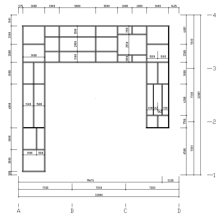
The above figure shows the plan view on a platform construction as it is automatically dimensioned by using several local areas.
You can make separate settings for horizontal and vertical shapes as well as for shapes visible in cross-section – each one in longitudinal and transversal direction. In addition, there is another global out-lying area having its own default settings.
The global outer/inner area is determined by means of a simple snap area without special analysis algorithm.

Alternatively, you can have determined local areas by means of an analysis algorithm and dimension them instead of the global inner area (but in addition to the global outer area).
The direction of the local area (horizontal dimensioning direction) is determined by the proportions of sides. The limit for a direction change to main direction is at 2/3 of the long side. If there is, however, a further subdivision of the area in segments, direction change will not be effected any more.
Indications of Place and Direction
Indications of place such as beginning, end, above, left, etc. always depend on the alignment of the component part or area.

In the neighboring figure, the position of the top (horizontal, long side) and the position of the left side (vertical, short side) of a component part are displayed, dependent on its insertion direction.
In addition, the figure also shows that the direction is not inevitably running from starting point to endpoint of the insertion (starting point here is checked by the black point). The standard reference point of the dimensioning (bottom left) is indicated by a black triangle.
When it is a matter of local dimensioning areas of connected shapes, the standard starting point is always the end of the shape which is situated nearer to the corresponding reference part. So to speak, this reference part is the higher ranking part with regard to the main part.However, all indications of place continue to follow the logic described above. The decision whether a component part now is situated ‘above’ or ‘below’ another component part, depends on the direction of the selected reference part.

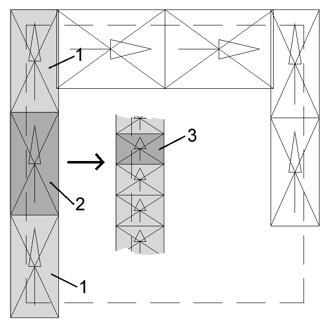
The example on the previous page shows a component part group with the main part (1) and several add-on shapes (2) and (3), which for their part are containing stiffeners (4).
A local dimensioning reference with ‘Component Part Start’ as reference point was selected for dimensioning the stiffeners.
As you can see, dimensioning is done along the component parts containing the stiffeners and each dimensioning chain starts near the reference part. In this example, the component part (2) is situated above the main part (1) and the component part (3) is situated below component part (2).
Position of Dimensioning Chains
You can either by force preset the position of the dimensioning chains within an area or you make select them automatically.
Component parts can be dimensioned on the side on which – with regard to their reference part – they are situated. In addition, a favourable side is defined, depending on the position, as it is displayed in the following figure:

Dimensioning chains which are situated close together can be summed up according to rules which have to be defined. Thus, a clear drawing will be possible and collisions of dimensions will be avoided right from the beginning.