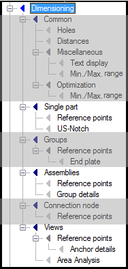
The following survey shows all independent part areas of
dimensioning in standard dialog display. When you selected the ‘intelligent’
arrangement of parameters, some of these areas are hidden or they are situated
on another position of the tree structure. However, it is always exactly the
same data record.
|
Common — Lists the general
default settings which are valid for all areas (e.g. distance of one
dimensioning chain to the other, dimensioning styles, dimensioning of drill
holes etc.).
|
|
Single part — Dimensioning
of single parts details, individual dimensioning of the main parts in groups.
|
|
Groups — Dimensioning of
group and subgroup details, individual dimensioning of groups and subgroups and
single parts in assemblies, individual dimensioning of subgroups in groups;
individual dimensioning of add-on parts in groups.
|
|
Assemblies — Dimensioning
of assembly details.
|
|
Connection node — Dimensioning of
connection details.
|
|
Views — Dimensioning of
overviews and anchor plans.
|
The arrangement corresponds to the hierarchic structure of
the part area. By selecting an entry, you directly reach the parent or
subordinate dialog tabs of the corresponding part area.
Note: As an e.g. the entry
Cut is situated below the entry Reference Points in the part area Group,
the dimensioning chains for intersections in groups are set here.