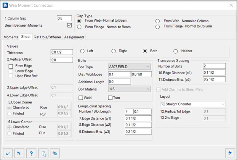
| Left/ Right/ Both/ Neither
|
Sets the placement of the Shear/ Stiffener Plate(s)
relative to the X axis of the connecting member.
Thickness disables all settings except the
Back Stiffeners.
|
| Values
|
- Thickness –
Sets the thickness of the Shear/ Stiffener Plates.
- Vertical
Offset – Sets the offset distance of the Plate and connecting
shape. If neither of the following options are checked, the distance is
measured from the Plate centerline to the axis center of the connecting shape.
A negative value is not permitted.
- From
Edge – When checked, the vertical offset is measured from the upper
edge of the connecting shape to the upper edge of the Plate.
- Lower
Edge – When checked, the vertical offset is measured from the lower
edge of the connecting shape to the lower edge/boring of the Plate.
- Up to
First Bolt – When checked, the vertical offset is measured from the
upper edge of the connecting shape to the first boring of the Plate.
- Upper/
Lower Edge Offset – Sets the edge offset from the end of the Moment
Plate.
|
| Upper / Lower Corner
|
-
Chamfered / Filleted – Sets one of the types of cut for the upper
or lower corner of the Stiffener Plate.
- Radius /
Rise - Run – Sets the distance relating to the cut. (Rise and Run,
in case of Fillet corners).
|
| Bolts
|
- Bolt
Type – Sets the bolt style from the drop-down list.
- Dia /
Workloose – Sets the hole diameter of the selected bolt from the
drop-down list of bolt diameter table. The second field sets the clearance
between bolt and hole diameter.
- Additional
Length – Sets an additional length to the bolts extension outside
the nut.
- Bolt
Material – Sets the material to be used for the bolts selected from
the drop-down list.
- Weld – When
checked, the shapes are welded, instead of bolting.
Note: When set
to Weld, disables the Bolts settings.
- Turn – When
checked, the bolt direction is inverted. Available when not welded.
|
| Longitudinal Spacing
|
- Number /
Slot Length – Sets the number of bolts to be placed on the X axis,
and in the second field, sets the slot length.
- Inner
Distance (w1) – Sets the distance from the start of the shape to
the center of the first bolt.
- Inner
Distance (w2) – Sets the distance from the end of the shape to the
center of the last bolt.
- Distance
Between (w3) – Sets the distance between the center of the bolts.
Note: Enabled
for more than one Number of bolts.
|
| Transverse Spacing
|
- Number of
Bolts – Sets the number of bolts to be placed on the Y axis.
- Edge
Distance (e1) – Sets the distance from the edge of the shape to the
center of the first bolt.
- Distance
Between (e2) – Sets the distance between the center of the bolts.
|