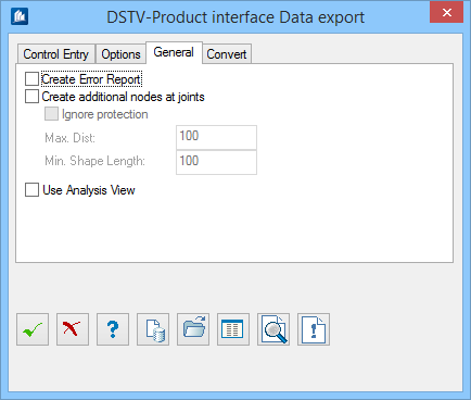
| Create Error Report
|
Creates an error report during exports and file
generation. You can see here which model data cannot be evaluated by
OpenBridge Modeler for the interface.
If such an error report was created, you can
display it by clicking the
 (Error
Report) button in the dialog. (Error
Report) button in the dialog.
|
| Create additional nodes at joints
|
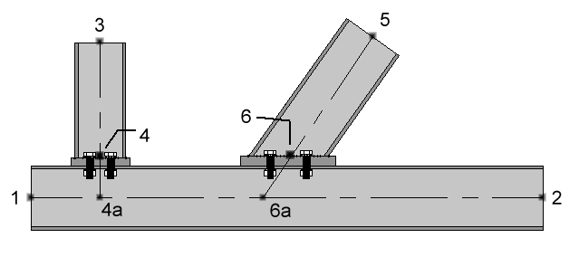
Continuous shapes at connections or theoretical
points of intersection with other shapes are divided.
|
| Ignore Protection
|
A possibly existing protection against division at
possible nodes is ignored at export of analysis display.
Since the division is mostly desired, you should
deactivate this option only in exceptional cases.
|
| Max. Distance
|
Sets the maximum distance, which is allowed for the
end point of a shape towards the continuous shape to be recognized as shape to
be divided.
|
| Min. Shape
|
Sets the minimum length of the bar, which has to be
created by the division. If this length is smaller, a division will not be made
and eccentricities will be determined instead.
This is reasonable when you export data to static
analysis programs as these are expecting a system of bars from gusset to
gusset (e.g. plate connections) although in reality it is a continuous shape.
As
OpenBridge Modeler of course cannot be as
specialized as a static program, you can switch off this option by this way, if
the static program offers better functions for this purpose.
|
| Use Analysis View
|
Instead of the CAD-position of the actual shape an
alternative static effective line is exported.
This line can be individually adapted for each
shape to your requirements for the transfer of static systems by means of the
‘Analysis Display’ command. You can avoid e.g. open nodes or eccentricities
(due to different insertion levels).
|