| Dimensioning Area
|
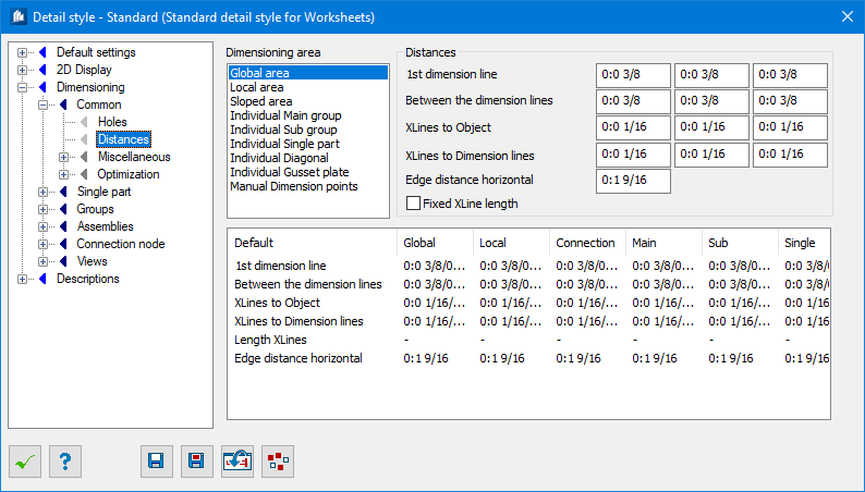
In the selection list you choose the dimensioning area you want
to work on. The current values are entered in the input fields on the right.
|
| Selection List
|
- Global
Area – The global outer area of dimensioning.
- Local
Area – The local inner area of dimensioning; as vertical dimensions of a
component part group are always local, they are controlled here as well.
- Sloped
Area – The local inner area of dimensioning at aligned dimensioning.
- Individual Dimensions... – The
different inner areas at individual dimensioning within component part groups,
etc.
- Manual
Dimension Points – The areas of manual dimension points.
|
| Distances
|
Most data can be indicated here independently for
horizontal, vertical and inner dimensioning direction. The fields on the left
correspond to horizontal direction (main direction), the fields in the middle
correspond to vertical direction (transversal direction), the fields on the
right correspond to inner direction (independent direction).
|
| 1st Dimension Line
|
Here, you enter the distances from the outer limit
of the component up to the 1st dimension line.
|
| Between the Dimension Lines
|
Here, you enter the distance between the individual
dimension lines of an area succeeding the first line.
|
| XLines to Object
|
Here you enter the distance from the start of
construction lines up to the outer limit of the component or of the
dimensioning area in question.
Entering the value 0 will not cut the construction
lines at the edges but they are extended to the corresponding points to be
dimensioned.
If you selected ’Fixed XLine
Length’ option, the meaning of the fields changes, and you enter
the length of the dimension construction lines.
|
| XLines to Dimension Lines
|
Here you enter the distance of the construction
lines of a successive chain up to the previous dimension chain.
Entering the value 0 will not cut the construction
lines at the previous dimension chains but they are extended to the outer limit
of the component or of the corresponding area to be dimensioned.
|
| Edge Distance Horizontal
|
Here you indicate the minimum distance hole group
dimensioning or subpart dimensioning may have up to the end of the component
before it is moved to the outside.
|
| Fixed XLine Length
|
If this field has been checked, the construction
lines have exactly the length specified in the input fields ‘Length of
Construction Lines’. If this field has not been checked, the dimension chains
are cut at each other with the distances indicated in the distance fields.
|
| Dimension Table
|
In the table, you see a survey on all available
settings to be able to control them at a glance. Information about horizontal
and vertical dimension is summed up (Horizontal/Vertical).
- Rows – the different
parameters for setting.
- Columns – the
different dimensioning areas.
|