Reference Points of Dimensioning
In principle, each dimensioning chain is created by fitting together individual dimensions which start in a selected reference point and end in the dimensioning point in question. In case of overlapping, the line segments are divided accordingly to form a continuous dimensioning chain.
Reference Point (Starting Point)
In most of the cases, the starting point of a dimensioning chain is the beginning of the component part; at groups, this often is the beginning of the main part (resp. of the local reference part in case of local references).
Reference Points of Dimensioning Chains
| Setting | Description |
|---|---|
| Beginning Ref. Part | The dimension begins in the start point of the reference part. |
| Beginning Group | The dimension begins in the start point of the group. |
| Edge Ref. Part | The dimension begins in the edge point of the reference part (starting or end point) which is situated closer to the component part to be dimensioned. |
| Edge Group | The dimension begins in the edge point of the group (starting or end point) which is situated closer to the component part to be dimensioned. |
| Center Ref. Part | The dimension begins in the center of the reference part. |
| Reference Point | The dimension begins in the first reference point of the reference part. Often, this is also the projected point of the insertion or reference axis of the component part. |
| Edge Ref. Point | If two reference points exist, the dimension begins in the reference point which is situated closer to the component part to be dimensioned. If only one reference point exists, this corresponds to the default setting ‘Reference Point’. |
| Connecting Shape | The dimension begins in the point of intersection of the center axes of the reference part and of the connecting shape belonging to the component part to be dimensioned. |
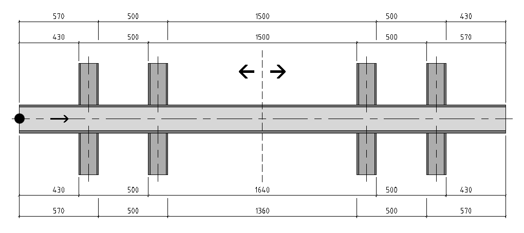
The example on the following page shows some important reference points of dimensioning chains. Web angle dimensioning could be made on the starting point of the group (1) or on the starting point of the main part (2). Dimensioning on the edge of the reference part would dimension the two web angles on the left on point (2) and the web angles on the right on point (3) – in case of edge group, this would be the points (1) and (4).

In the present example, however, the variant connecting shape was selected and thus you obtain the two dimensioning chains (A) as result. Dimensioning chain (B) results from the fact that, in addition, the reference points are dimensioned, too.
Dimension Point (Target Point)
The target point of dimensioning is determined by the component part to be dimensioned or by the detailing (e.g. drill hole). Depending on the kind of component part or detailing, you often have a great number of different options for selection. Most of the options are self-explanatory so that we will only describe some common features here. For more detailed information, please refer to the short descriptions of the different sections.
The importance of the component part’s reference edges depends on the dimensioning direction of the dimensioning chain (see also: Indications of Place and Direction). From top to bottom, the example shows the dimensioning chains reaching from the beginning of the component part to the reference edges front edge, rear edge, outer edge, inner edge.
To allow fast and practical dimensioning of different shapes, an automatic selection of dimension points is available (depending on the component part) which is sufficient for most cases.
Here, you see the defaults for the different shape types, positions of component parts and directions of dimensioning chains:
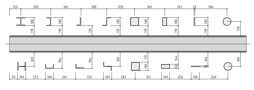
Apart from dimensioning on the insertion-reference point, on possibly existing drill holes or even on combinations of both, you can select some special forms as target point.
The example shows the dimension point contact area for the dimensions in longitudinal direction. The edge which is turned to the reference or connecting shape will be dimensioned.
Additional Dimensions
You can add different additional dimensions to each dimensioning chain. These are added later to obtain "closed dimensioning chains.
The additional dimensions permit uniform dimensioning running; on the other hand the dimensioning reference can be made clearer, you can eliminate insignificant remaining dimensions and thus reduce the number, when you don’t use them.