Conical Flange offsets dialog
Depending on the selected shape, this dialog tab can look different. This is the dialog tab of a standard shape.
For Standard Shapes

For Non-standard Shapes


 Set any height

 Insert edge
 Delete edge
 Edit web plate
 Set flange offset
 Insert new entry
 Edit current entry

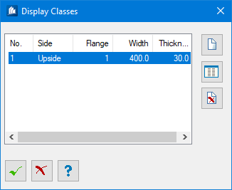
Flange offsets dialog

| Setting | Description |
|---|---|
| Bottom Flange Shape End | The projection of the bottom flange at the end point of the shape is indicated. |
| Bottom Flange Shape Start | The projection of the bottom flange at the starting point of the shape is indicated. |
| Top Flange Shape Start | The projection of the upper flange at the starting point of the shape is indicated. |
| Top Flange Shape End | The projection of the upper flange at the end point of the shape is indicated. |
Upper and bottom flange are considered separately. The indication of the flange refers to the number of flanges from the starting point per side.
It is recommended to edit the thicknesses after having determined the bend points. A modification of the form by insertion or deletion of points modifies the table as well because the number of flanges is modified.