Dimensioning Groups
All essential parameter settings are made per partial sector via freely definable dimensioning groups with any assignment of component part types, i.e. you can define if need be how complex the structure of dimensioning has to be.
Compared with previous versions, this proceeding is considerably more practice-oriented because first you decide (a) how you want to dimension and then (b) which component parts have to be dimensioned in this way.
In the easiest case of component part group dimensioning only the settings for the overall dimension and the settings of a common dimensioning group for all add-on parts – independent of their type – is available. However, if a more complex dimensioning is required, you can add further dimensioning groups or special dimensions as you like and thus specialize the default settings even further.
You can generate any dimensioning groups with identical settings you like by using the component parts of the inner structures. The advantage is that identical settings for different component parts can fast be made or modified. The number of parameters still allows a clear view.
At the same time, an essential limit of previous versions is superseded: synonymous component parts which were differently modeled in the 3D-model can be dimensioned together by means of one setting. Let us take stiffeners in a shape here as an example which have once be manually created as polyplates and once by using the stiffener function.
Define Guidelines for Dimensioning
In principle, a dimensioning group complies with a clear guideline for the component parts to be dimensioned.
By means of the parameter set of the group you define how the component parts have to be dimensioned. This parameter set is divided into different rules for straight and bent dimensioning directions, favorable and unfavorable views, etc. By means of the assigned component parts you define which component parts have to be dimensioned with these rules. This can either be a very general selection (e.g. all shapes) or a very special selection (e.g. sheet metal plates bigger than 200x200 mm).
Dimensioning is worked off according to the principle of exception: All component parts or detailings for which no own rule has been defined, are treated together with the settings of the so-called standard group. This group exists in any partial sector of dimensioning and permits a fast selection at identical rules.
If certain component parts don’t have to be dimensioned, they have to be assigned to a group as well, because ‘No dimensioning’ is a kind of rule, too. For example, you could define the different rules for all component parts having to be dimensioned and then set the standard group to ‘No dimensioning’.
Special Component Part Groups, Detailings, and Special Dimensions
Each component part can be assigned to a standard dimensioning group. However, apart from their common properties shapes and sheet metal plates also have features which don’t mean anything to the other of both types. This is the reason why in a standard group only the common properties of dimensioning are available.
If you want to make use of the extended properties, you can e.g. insert a shape dimensioning group to which exclusively shapes can be assigned. However, this group offers many more setting possibilities – especially just for shapes.
The detailings of single parts (drill holes etc.) as well as certain other dimensions are dimensioning rules to which nothing else can be assigned. However, here it logically is a matter of dimensioning groups as well which can be added if need be.
These very often are very special groups and can only exist once per dimensioning area. The overall dimension of a detail is also a special dimension. As it is often required, it is a kind of standard dimension which always exists.
User-defined dimensions constitute a special case. As many dimension points can be dimensioned on as many reference points as desired, although these points need to be defined individually on the 3D model.
Nesting
Complex group structures such as e.g. an assembly can consist of several component part groups and subgroups.
Nesting in dimensioning (individual dimensioning) permits complete dimensioning even of subordinate groups within a parent group. Additional detail drawings can thus be omitted.
As there is only one set of parameters per hierarchy type available for subordinate structures, individual structures can be excluded or limited in dimensioning via filter.
Typical applications of nested dimensioning are for example the dimensioning of the detailings of add-on parts in groups or the dimensioning of the position of component part add-on parts in assemblies.

Besides the add-on dimensions (1) of polyplates, this detail of a component part group still has an individual dimensioning like a single part dimensioning (2).
Multiple Dimensioning
Normally, a component part is dimensioned only once, e.g. drill hole dimensioning. This option is already known from previous versions.
The flexible structure now also permits multiple dimensioning of component parts. Thus it is possible to (a) dimension all shapes via the drill holes as you did up to now and (b) to dimension certain shapes additionally via the center axes by using completely independent default settings.
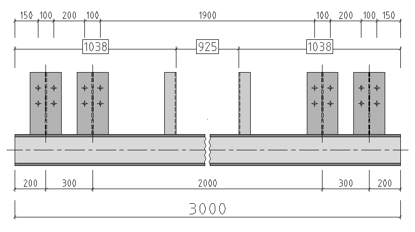
Multiple dimensioning of a straight shape. The outside girders are equipped with an additional dimensioning chain via the center axes..
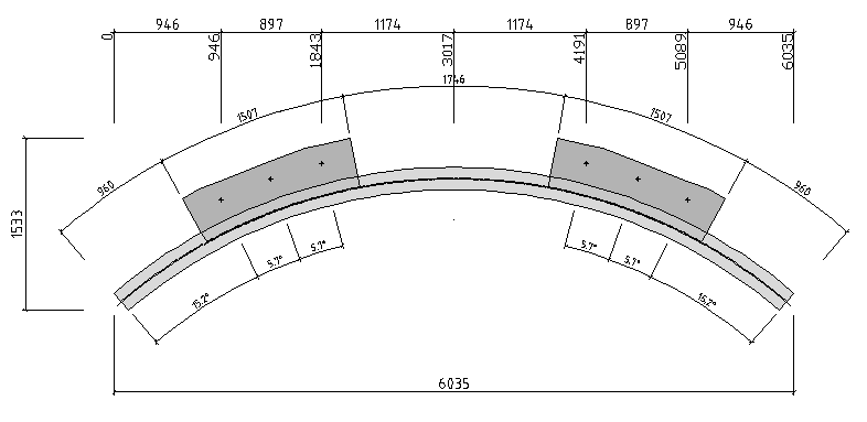
Multiple dimensioning of a bent shape. The connection plates are equipped with an additional dimensioning chain with the angle dimensions towards the edge of the component part.
The following example of an assignment shows the structure of a more complex dimensioning. Three additional dimensioning groups with independent rules are defined and an additional special dimension is fixed.

As the standard group has to process all other component part types, this in principle is a standard dimensioning group.
Copy Settings
Most of the dimensioning groups can be copied within a partial sector. At first, no component parts are assigned to this copy, even if there are already some assignments in the original group.
Copies always have the same type (e.g., if the original group is a shape group the copy again is a shape group, too). Then, you can rename the copy and assign the desired component parts to it.
Special dimensions and single part detailings can exist only once and therefore cannot be copied.