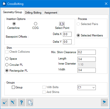
Cross Bolting - Geometry tab
Used to set insertion options, add shim, form group and process selected pairs or members.
| Setting | Description |
|---|---|
| Insertion Options | Allows setting one of the methods and offsets of selecting insertion point; as Centerline, Center of gravity of shape or picked manually in the view. The Centerline and COG options are only available when all the valid members in the selection are shapes, and only Select Point insertion ia available when a valid plate is in the selection. |
| Centerline | Applies the bolting pattern according to the intersection of the centerlines of the valid shapes. |
| COG | Similar to the centerline option except the crossbolting is done according to the intersection of the center of gravity of the shapes. |
| Select Point | You can optionally define an insertion point, by specifying the base point for the bolt distribution calculations. Applicable when a connecting shape has the same Z orientation as the supporting shape and that their centerlines are aligned. |
| Basepoint Offsets | Sets the insertion point X and Y offsets, respectively. |
| Process | Based on the selection, one of the process methods
is applied.
You begin selecting a supporting member followed by one or more connecting member(s) individually with the <Ctrl> key pressed or with a crossing window. If the supporting member is selected again as a connecting member, it will be dropped from the selection. Depending upon the selection, the process mode is set to either Pairs or Members.
The members are listed in the group's combo list. If a
member in a combo box is displayed with an
*, the member will be dropped upon
accepting the connection. For example, member
C5* will be dropped when accepting the
connection. Selecting a member with an * will revert the selection to the
support member.
|
| Selected Pairs | Set pairs mode of selection, where two members will
be paired if they have the same shape, the same size, parallel z orientations
and the same trajectory.
Paired Mode
|
| Selected Members | In member mode, it is possible to use plates. · The
radial pattern is also available.
Member Mode
|
| Shim | When there is a gap between members of the connection, you can optionally add shims in between. There are three options for creating shims: Space, Circular and Rectangular. |
| Space | When set, shims won't be added. |
| Circular | When set, you should specify the Outer Diameter. When outer diameter is equal or less than Inner Diameter, the outer diameter value will revert to the inner diameter value and shims will not be created. |
| Rectangular | When set, you should enter the Length and Width of the shims. Both these values must be greater than the inner diameter. If a smaller value is entered, it will be converted to the inner diameter. |
| Check Collisions | When set, detects collisions, if any to avoid having
shims that would fall i.e. within the flange of a beam.
Generally, members should not collide with each other, but it is still allowed. When members collide with each other, it could result in shims that also collide with the members. |
| Shim Clearance | Sets a minimal allowable shim clearance to make sure all shims have a minimal thickness. In order to be able to have shims, the members surfaces' on which the crossbolting is applied must have parallel normal vectors and their normal vectors must also be parallel to the drilling direction. Hence, it is possible that some members have shims in between them while others don't within the same crossbolting connection. |
| Group | Grouping can only be done on the supporting member or the connecting members. You have the option to select the member to which bolts or bolts and shims will be grouped. (Shims cannot be grouped when bolts are not grouped). During the rebuild process, when group member is dropped from the connection, the bolts and possibly shims will be grouped with the supporting member instead. |
| With Bolts | When set, forms a group with the selected member and adds bolts to it. |
| With Shims | In case the group is created by the connection, it is disbanded if form group or with bolts is unselected or if the connection is deleted. |
| (Group List) | Lists currently selected members in connection.
If a group already exists, the bolts and shims are added to the existing group. If the group does not exist, it will be created with the supporting member or a connecting member per selected member as the main part and then the bolts and shims will be added to the group. |
