Profile From Surface
 Generates a profile whose
elevations are determined by draping onto a surface.
Generates a profile whose
elevations are determined by draping onto a surface.
You can access this tool from the following:

Use the Profiles from Surface tool to generate a profile whose elevations are determined by draping onto a surface. The surface may be a terrain model, a mesh, or mesh solid.
Quick Profile from Surface is a companion tool that provides the same result but simplifies the input by assuming that the entire element is draped and that the offsets are zero.
-
Select the Profiles by Surface icon.
-
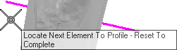
When you move the cursor into the View, it is equipped with a command prompt requesting that you "Locate First Element to Profile", move the cursor to a horizontal line that crosses the terrain model.
-
When you've selected all of the elements you wish to profile, right-click in an empty area.
-
When prompted to "Locate Reference Surface", data point on the terrain model.
-
Use one of the following methods to set the Start Distance:
-
Use one of the following methods to set the End Distance:
-
When prompted to choose a "Point Selection", strike the down arrow key to navigate the options then strike the Enter key to execute your choice.
-
When prompted to choose a "Point Adjustment", strike the down arrow key to navigate the options then strike the Enter key to execute your choice.
-
When prompted to choose a "Draping Option", strike the down arrow key to navigate the options then strike the Enter key to execute your choice. This applies only for point selection equal ALL. The available options are:
-
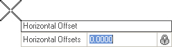
Use one of the following methods to establish the Horizontal Offset:
-
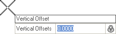
Use one of the following methods to establish the Vertical Offset:
-
To view the new profile of the element, click the Open Profile Model icon.
-
Move the cursor into the workspace and note that it is accompanied by a prompt that says, "Locate Plan Element". data point on the newly profiled element.
-
The cursor is now equipped with a prompt that says, "Select or Open View".


Properties
To View the new element's properties, equip the Element Selection tool.

Select the elevated element in the Profile View then let the cursor hover over it. Click the Properties icon to access rule data for the chosen element.