|
Option
|
Description
|
|
Linear
|
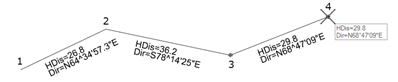
Graphically place data points in 2D or 3D view. The tool chains the points, so you can select multiple points. Annotation and reports generate information between each pair of points. For example, if four data points are placed, the results are displayed for points 1 and 2, 2 and 3, 3 and 4. Attached to the cursor is the last distance and direction, in this example, at point 4.
|
|
Arc
|
Three points are needed for the arc option, which can be done by:
- Point on curve - Start point, end point, thru point
- Radius point mode - Start point, center point (radius point), end point
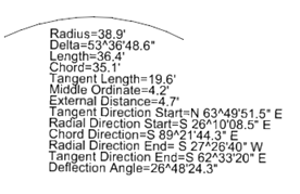
The direction of the arc must be defined. Once the arc is drawn, the cursor is set up to draw a second arc. Reset to exit the tool. Once complete, extensive arc data is displayed.
|
|
Radial
|
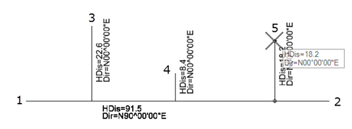
The first point is the base of the radials, often referred to as the backsight point, while all subsequent points draw from the point back to the base point. Resetting exits the tool. The large dot is the base point.
In the case of radial, each point is projected back to the base point and the distance and direction is computed along the projection, rather than linearly from point to point.
|
|
Perpendicular
|
In the case of perpendicular, the point is projected onto the element and the distance and direction is computed along the projection, rather than linearly from point to point. Two modes are supported: Perpendicular Between Points - the first two points define a line upon which all subsequent points are projected (perpendicular). A minimum of 3 points is needed, two for the line and at least one to project. More may be projected, reset when complete to exit the tool. In this example, points 1 and 2 define the line, while points 3,4, and 5 are projected. The cursor data reflects the last point being projected.
Perpendicular by Element - An existing MicroStation or Civil element is selected for the base element and any data points are projected (perpendicular) onto the selected element. In this example, the previously drawn arc is selected and 3 data points are placed.
|
|
By Element
|
Inverses existing MicroStation or Civil elements. If a line is selected, the distance and direction are displayed. If an arc is selected, the arc data is displayed. If complex elements, shapes, etc. are selected, each component is annotated. |