Civil Geometry Design Standards
Design standards can be used to maintain required curvature and other alignment checks when performing geometric layouts. They work at two levels:
- Provide values for the element creation tools (for example, minimum radius and transition lengths)
- Check the suitability of complex elements (for example, check for kinks in the alignment)
Design standards are very alignment oriented. You may find limited value for using design standards for non-alignment computations.
When a design standard is violated, feedback is provided in two ways:
- An icon in the graphics, on the element that has the problem. Hover over the icon to reveal a tool tip report of the error.
- In the Civil Message Center
Design Standard Toolbar

On the menu, select Geometry > General Tools > Standards > Design Standards Toolbar to open the design standards toggle bar.

This toolbar allows you to set an active design standard used by all commands.
- Select the desired standard.
- Click the button on the left to toggle the standard on or off. When on, all commands will make use of the values contained in the standard. When off, the selected standard is ignored.
Creating Design Standards
Design standards allow you to set up your organizations desired standards to control alignment configurations based on design speed and other considerations.
- Create a DGNLIB for your standards.
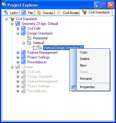
- Open the File menu, choose Project Explorer, and open the Civil Standards tab. You can create a new standard by right-clicking then choosing New, or by copy/paste of an existing standard.
- Once created, select the standard to set or edit its properties.
- Open the item's Details panel to review the settings.
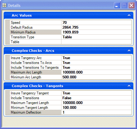
The following list describes the properties for each standard:
- Speed this is the design speed for the standard; this is for user information and also used in equations
- Default Radius this is the radius used to populate commands when they start; degree of curve input to the design standards settings are not supported
- Minimum Radius this is the minimum radius for the corresponding design speed; utilizing values lower than this radius will cause a warning to be displayed
- Transition Type can be by Table or Equation; the transition length equation is a hard-coded equation found in the AASHTO Manual 2004.
Metric equation:
L = V3 / (46.7 * RC) where:
L = Length. m
V = Speed, km/h
C = _centripetal acceleration (rate of increase of lateral acceleration) m/s3
R = curve radius, m
The only input within the design standard is C.
The formula can be found:
AASHTO 2004 – 3-27, page 185.
AASHTO 2011 – equation 3-25, page 3-70.
Imperial equation:
L = 3.15*V3 / R*C
- Table if the Transition Type is set to table, then this is used to populate the table (See below)
- Insure Tangency Arc if set to True, then the standard checks all arcs to insure against kinks
- Include Transitions to Arcs If set to True, then transitions are applied to arc commands
- Maximum Arc Length
- Minimum Arc Length
- Insure Tangency Tangent If set to True, then tangents are checked for kinks
- Include transitions If set to True, then line commands will have transitions added
- Maximum Tangent Length
- Minimum Tangent Length
- Maximum Deflection Where two tangents join without a curve, what is the maximum angle between the lines
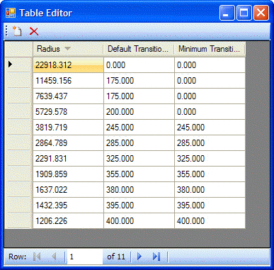
Transition Tables This is a radius table that lists default and minimum transition lengths corresponding to each radius. If the actual used radius is not found in the list, then the transition length for the radius closest to but not longer than the specific radius is used.