Truss Connection - End Zone tab
Used to specify chord and brace geometry, panel count, caps, plate thickness, shape types, and sizes for end zones.
Chord tab
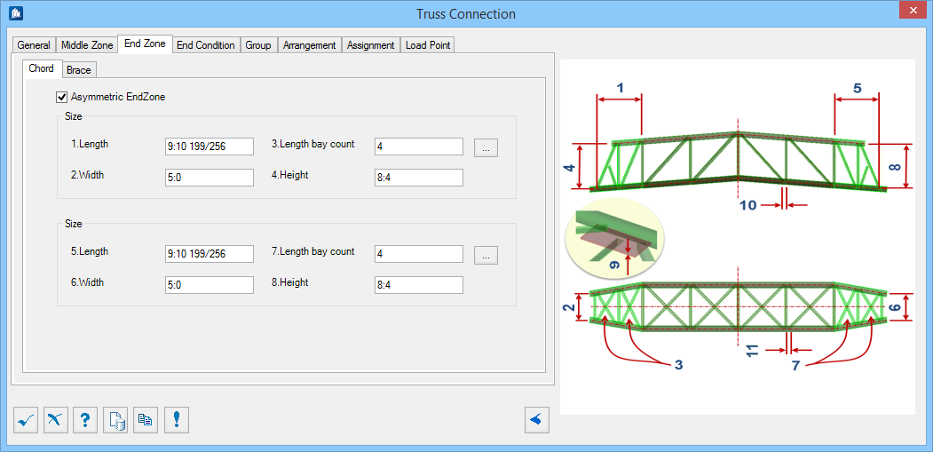
 Panel Distances

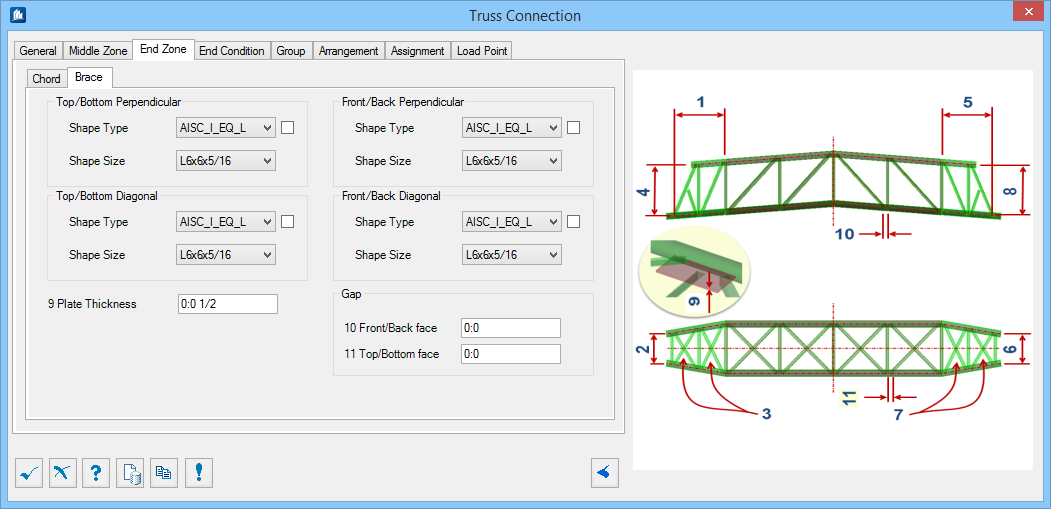
Brace tab
| Setting | Description |
|---|---|
| Brace shapes | For each group, you can select the
Shape Type and
Shape Size from the associated drop-down
lists. Separate shapes can be selected for:
|
| Plate Thickness | Sets the gusset plate thickness to use for brace connections. Denoted with 9 in the diagram. |
| Gap | Sets the gap to use for both the Front/Back Face and Top/Bottom Face. Denoted with 10 and 11 in the diagram. |