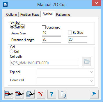
Manual 2D Cut - Symbol tab
You can generate the cutting code either via a generated graphic or via cells to be selected.
| Setting | Description |
|---|---|
| Symbol | The cutting code is created as a symbol consisting of cutting arrow and code. |
| Continued | The two partial lines are connected through the cut part. |
| By Side | The cutting code is written beside the cutting arrow; otherwise it is written above the cutting arrow. |
| Arrow Size | Specify the size of the arrow. |
| Distance/Length | Here, you specify the distance of the cutting lines, from their beginning to the utmost bordering edge (e.g. the dimensioning), and what has to be the length. |
| Cell | A freely selectable cell is used for the cutting code instead of a cutting arrow. In the input fields Top Cell and Down Cell you see the selected cell path. You can assign a cell symbol by clicking Select folder icon to pick a user specific cell symbol. |
| Cell Path | Here you indicate the directory with the files containing the cell definitions for the cutting arrows. Select the directory via the neighboring button. |
| Top Cell | Here you select the cell for the upper cutting arrow. |
| Down Cell | Here you select the cell for the lower cutting arrow. |
